Brake device and brake method thereof
A brake device and brake pin technology, applied in the direction of engine starting, engine components, machine/engine, etc., can solve the problems of inconvenient use of armored vehicles, engine failure, heater failure, etc., to improve vehicle mobility High performance, saving battery power, and simple structure
- Summary
- Abstract
- Description
- Claims
- Application Information
AI Technical Summary
Problems solved by technology
Method used
Image

Examples
Embodiment Construction
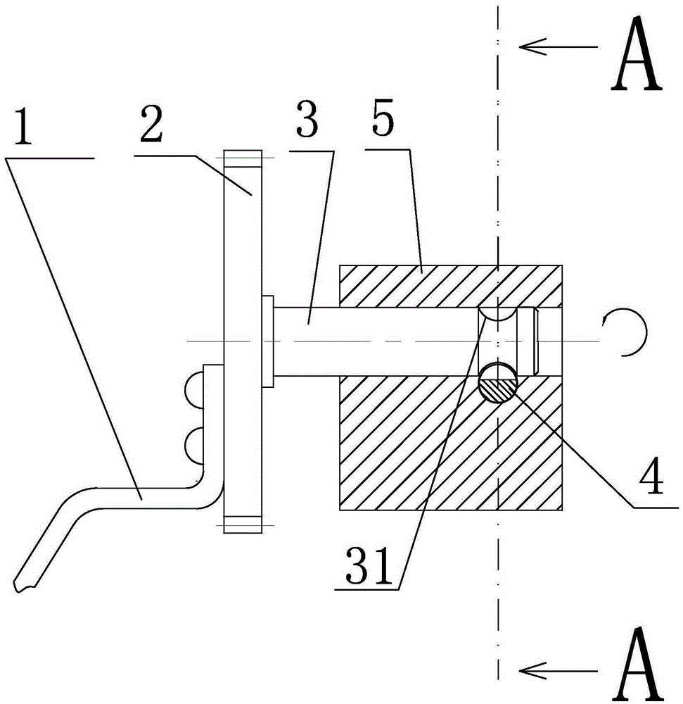
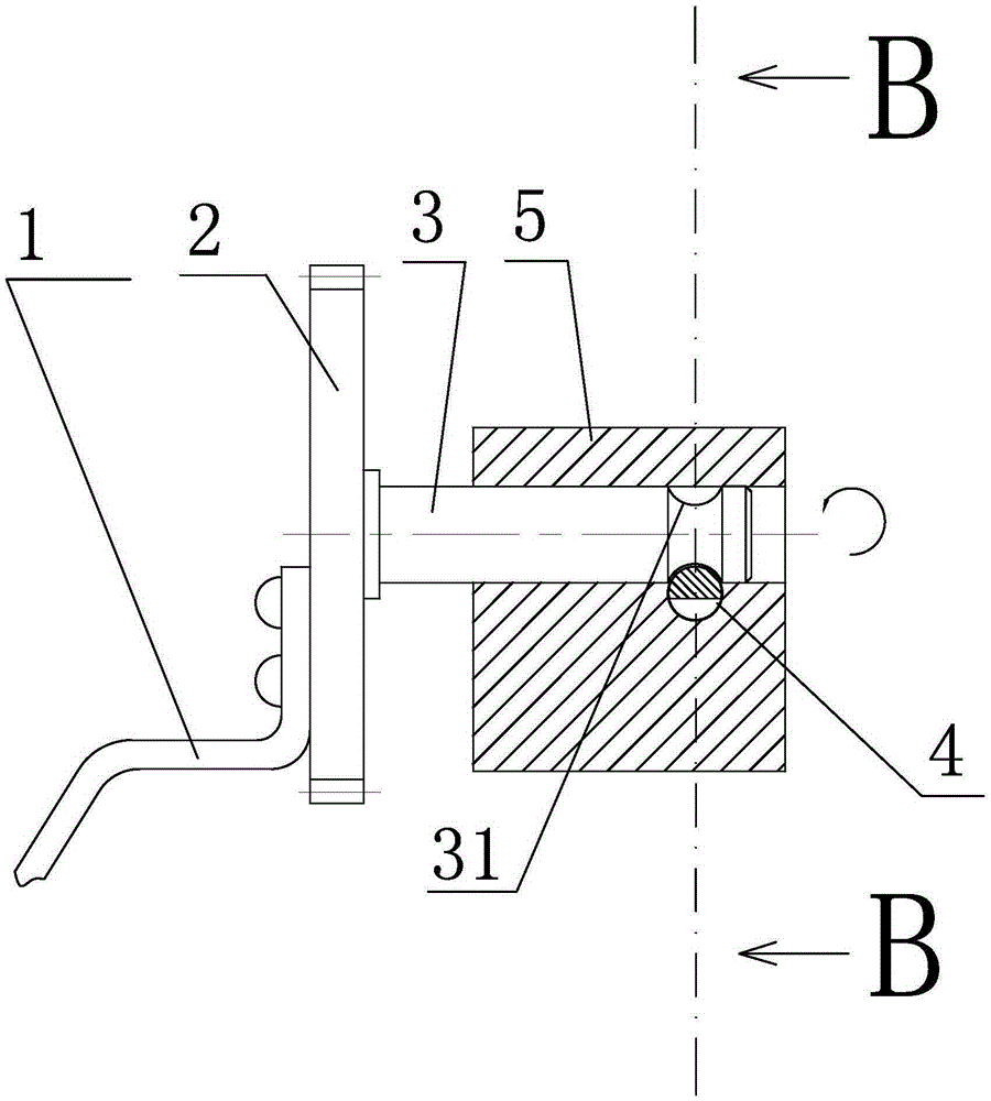
[0026] like figure 1 As shown, a braking device of the present invention includes a hand crank 1, a gear 2, and a shaft 3 connected to each other. In order to ensure the stability of the connection between the three and ensure the effect of kinetic energy transmission, a common Various rigid connection methods. The left end of the shaft 3 is connected to the center of the gear 2, and the right end extends into the shaft hole in the oil pump 5. The right end of the shaft 3 located in the oil pump 5 is provided with a concave portion 31 around its circumference. Preferably, for ease of processing and cooperation with the brake pin 4 described below, the cross section of the recessed part 31 is a circle, and the diameter of the circle decreases from the upper and lower ends of the recessed part 31 along its axial direction to the center.
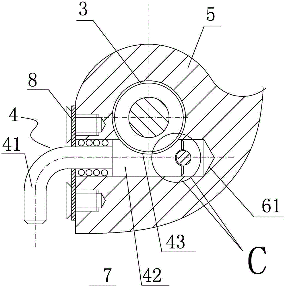
[0027] like figure 2 As shown, the oil pump 5 is provided with a locking mechanism, the locking mechanism includes a brake pin 4, and the o...
PUM
 Abstract
Description
Claims
Application Information