Braking device and braking method thereof

A braking device and braking pin technology, which is applied to the starting of the engine, engine components, machines/engines, etc., can solve the problems of inconvenient normal use of armored vehicles, inability to start the heater, and inability to start the engine, so as to improve the mobility of the vehicle. performance, saving battery power, and simple structure

Active Publication Date: 2017-08-08
北京北机机电工业有限责任公司
View PDF5 Cites 0 Cited by
  • Summary
  • Abstract
  • Description
  • Claims
  • Application Information

AI Technical Summary

Problems solved by technology

At present, the heater is powered by the battery to start. On the one hand, the power of the battery on the engine is very precious and cannot be used excessively. It is necessary to save electricity as much as possible. On the other hand, the heater cannot be started when the power is insufficient, and the engine cannot be started. , which brings great inconvenience to the normal use of armored vehicles

Method used


Image

  • Braking device and braking method thereof
  • Braking device and braking method thereof
  • Braking device and braking method thereof

Examples


Embodiment Construction

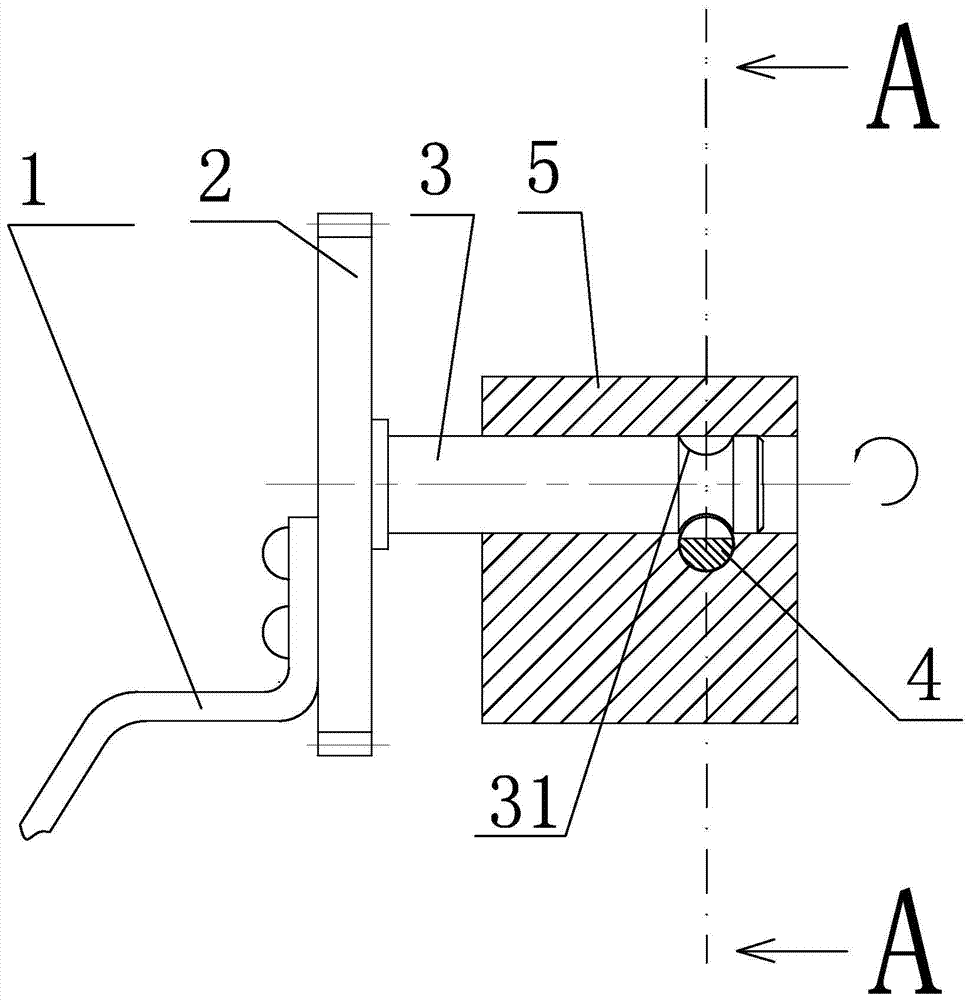
[0026] Such as figure 1 As shown, a braking device of the present invention includes a hand crank 1, a gear 2, and a shaft 3 connected to each other. In order to ensure the stability of the connection between the three and ensure the effect of kinetic energy transmission, a common Various rigid connection methods. The left end of the shaft 3 is connected to the center of the gear 2, and the right end extends into the shaft hole in the oil pump 5. The right end of the shaft 3 located in the oil pump 5 is provided with a concave portion 31 around its circumference. Preferably, for ease of processing and cooperation with the brake pin 4 described below, the cross section of the recessed part 31 is a circle, and the diameter of the circle decreases from the upper and lower ends of the recessed part 31 along its axial direction to the center.

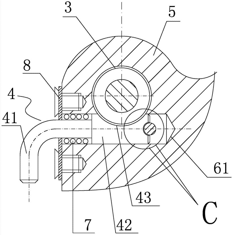
[0027] Such as figure 2 As shown, the oil pump 5 is provided with a locking mechanism, the locking mechanism includes a brake pin 4, and...


PUM


Abstract

The invention discloses a brake device which comprises a hand crank, a gear and a shaft which are connected. One end of the shaft is connected with the center of the gear, and the other end of the shaft stretches into a shaft hole of an oil pump and is provided with a concave part. A locking mechanism comprises a brake pin and the oil pump is internally provided with a pin hole crossed with the shaft hole, wherein the center line of the pin hole and the center line of the shaft hole are not located on the same plane. One end of the brake pin stretches into the pin hole, and the other end of the brake pin is located outside the pin hole. The upper surface or the lower surface of the part, located in the pin hole, of the brake pin is provided with a circular arc groove. The maximum diameter of the groove is not smaller than the outer diameter of the shaft. A limiting part is fixedly arranged at the deepest position of the pin hole. An arc groove matched with the limiting part is formed in one end face of the brake pin. A positioning spring is arranged on the brake pin in a sleeving manner, one end of the positioning spring is fixed to the pin hole, and the other end of the positioning spring is fixed to the surface of one side of a step part of the brake pin. The brake device is simple in structure, reliable, easy to operate, high in environment adaptability and capable of running reliably in severe environments such as the low-temperature environment and ensuring fast starting of an armored vehicle.

Description

technical field [0001] The invention relates to a vehicle braking control system or its components, in particular to a braking action starting device and a braking method. Background technique [0002] The vehicle heater is mainly used to preheat the engine under low temperature conditions to ensure the vehicle starts quickly. Past practice and test data show that the engine wear caused by a cold start is equivalent to the normal driving of the vehicle for 200 kilometers, and 60% of the engine wear is caused by cold start. Therefore, installing a heater can fully protect the engine and prolong the use of the engine life. For armored vehicles, the heater product is used to heat the waterway and auxiliary system before the engine starts in a low temperature environment (-5°C ~ -45°C). At present, the heater is powered by the battery to start. On the one hand, the power of the battery on the engine is very precious and cannot be used excessively. It is necessary to save elect...

Claims


Application Information

Patent Timeline
Patent Type & Authority Patents(China)
IPC IPC(8): F02N19/02F02N19/10
CPCF02N19/02F02N19/10
Inventor 付迎春陈红伟金晶
Owner 北京北机机电工业有限责任公司
Why Eureka
Try Eureka