Floating oil seal with ceramic composite wear-resisting face and metal stamping ring bodies

A technology of metal stamping and ceramic compounding, applied in the direction of engine seals, engine components, mechanical equipment, etc., can solve the problems of high cost and low productivity, and achieve the effects of improving service life, improving wear resistance and easy processing

Inactive Publication Date: 2016-03-09
李纯
View PDF6 Cites 1 Cited by
  • Summary
  • Abstract
  • Description
  • Claims
  • Application Information

AI Technical Summary

Problems solved by technology

This process saves rare metals, but it is limited by equipment, low productivity and high cost
[0009] To sum up, the current floating oil seals with various molding methods have various deficiencies and defects in terms of service life, performance, productivity, cost, etc.

Method used


Image

  • Floating oil seal with ceramic composite wear-resisting face and metal stamping ring bodies
  • Floating oil seal with ceramic composite wear-resisting face and metal stamping ring bodies
  • Floating oil seal with ceramic composite wear-resisting face and metal stamping ring bodies

Examples


Embodiment 1

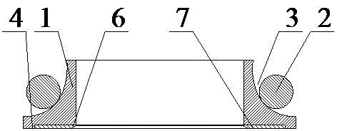
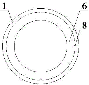
[0045] Such as image 3 As shown, the floating oil seal with ceramic composite wear-resistant surface and metal stamping ring body in this embodiment includes a pair of sealing ring bodies 1 with symmetrical upper and lower structures. The sealing ring body 1 is formed by secondary stamping of a metal sheet. A groove 3 for arranging the sealing ring 2 is arranged on the outer side of the sealing ring body 1, and the sealing ring 2 is arranged in the groove. The working surface 4 of the sealing ring body 1 is provided with a wear-resistant belt assembly groove 5 , and a wear-resistant belt 6 is fixedly installed in the wear-resistant belt installation groove 5 . The wear-resistant band 6 is made of zirconia ceramic powder with a zirconia content of 80% and an original grain size of 5-10 μm. After dry pressing, the blank is sintered at a high temperature of 1480°C. The friction surface 7 of the wear-resistant belt 6 protrudes from the working surface 4 of the sealing ring body ...

Embodiment 2

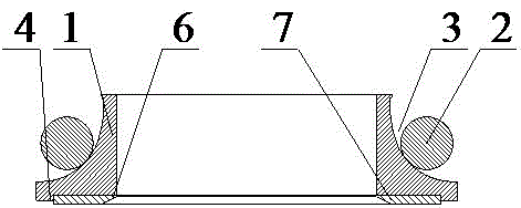
[0048] Such as Figure 4 As shown, the floating oil seal with ceramic composite wear-resistant surface and metal stamping ring body in this embodiment includes a pair of sealing ring bodies 1 with symmetrical upper and lower structures. The sealing ring body 1 is formed by stamping three times from a thin metal plate, and the surface After phosphating treatment, a groove 3 for arranging the sealing ring 2 is arranged on the outer side of the sealing ring body 1, and the sealing ring 2 is arranged in the groove. The working surface 4 of the sealing ring body 1 is provided with a wear-resistant belt assembly groove 5 , and a wear-resistant belt 6 is fixedly installed in the wear-resistant belt installation groove 5 . The wear-resistant band 6 is made of alumina ceramic powder with an alumina content of 99% and a primary grain size of 5-10 μm, which is formed by dry pressing and sintered at a high temperature of 1580-1620°C. The friction surface 7 of the wear-resistant belt 6 is...


PUM


Abstract

The invention provides a floating oil seal with a ceramic composite wear-resisting face and metal stamping ring bodies. The floating oil seal comprises the pair of sealing ring bodies of up-down symmetrical structures. The working face of each sealing ring body is provided with an annular groove used for containing a sealing face. The sealing ring bodies are formed through metal stamping. A circle of wear-resisting belt is fixedly assembled in a wear-resisting belt assembly groove. The wear-resisting belt is made of metal materials added with ceramic powder which is distributed in a dispersed phase state. The addition quantity of the ceramic powder is not larger than 5% of the total mass of the metal materials. The wear face of the wear-resisting belt is located on the same plane as the working faces of the sealing ring bodies or protrudes out relative to the working faces. According to the floating oil seal, the wear resistance degree of the working faces can be effectively improved, the service life can be prolonged, machining is easy, and the production cost is low.

Description

technical field [0001] The invention relates to the field of machinery, in particular to a ceramic composite wear-resistant surface and a metal stamping ring body floating oil seal used for sealing floating end faces in mechanical equipment. Background technique [0002] Floating oil seals are used in floating end face seals, which are mechanical seals with large consumption and wide application (nearly 10 million pieces per year in the country), such as figure 1 As shown, this seal is composed of two metal floating end face seal rings (referred to as floating oil seals) and two "O" type rubber seal rings installed on the central shaft. It has the characteristics of wear resistance, impact resistance, certain adaptability, long life, simple structure, low price, and convenient maintenance and replacement. It is widely used in the sealing structure. Due to the special environment in which the floating oil seal is used, it is a vulnerable part. The exposed installation loca...

Claims


Application Information

Patent Timeline
Patent Type & Authority Applications(China)
IPC IPC(8): F16J15/50
Inventor 李纯
Owner 李纯
Why Eureka
Try Eureka