IDC machine room temperature monitoring method and system based on distributed optical fiber temperature measurement

An optical fiber temperature measurement and optical fiber temperature technology, applied in the field of monitoring, can solve the problems of complex modeling process, high cost, long simulation time of cabinet temperature field, etc., and achieve the effect of small calculation amount, simple calculation, and real-time temperature monitoring.

Active Publication Date: 2019-01-01
BEIJING AEROSPACE YILIAN TECH DEV
View PDF5 Cites 0 Cited by
  • Summary
  • Abstract
  • Description
  • Claims
  • Application Information

AI Technical Summary

Problems solved by technology

[0005] The method in the prior art has the following defects: high cost, the method needs to use professional CFD software for simulation, the modeling process is relatively complicated, the simulation time of the temperature field of the cabinet is long, and the temperature cloud map of the cabinet cannot be displayed quickly and in real time

Method used


Image

  • IDC machine room temperature monitoring method and system based on distributed optical fiber temperature measurement
  • IDC machine room temperature monitoring method and system based on distributed optical fiber temperature measurement
  • IDC machine room temperature monitoring method and system based on distributed optical fiber temperature measurement

Examples


Embodiment Construction

[0039] In order to make the above objects, features and advantages of the present application more obvious and comprehensible, the present application will be further described in detail below in conjunction with the accompanying drawings and specific implementation methods.

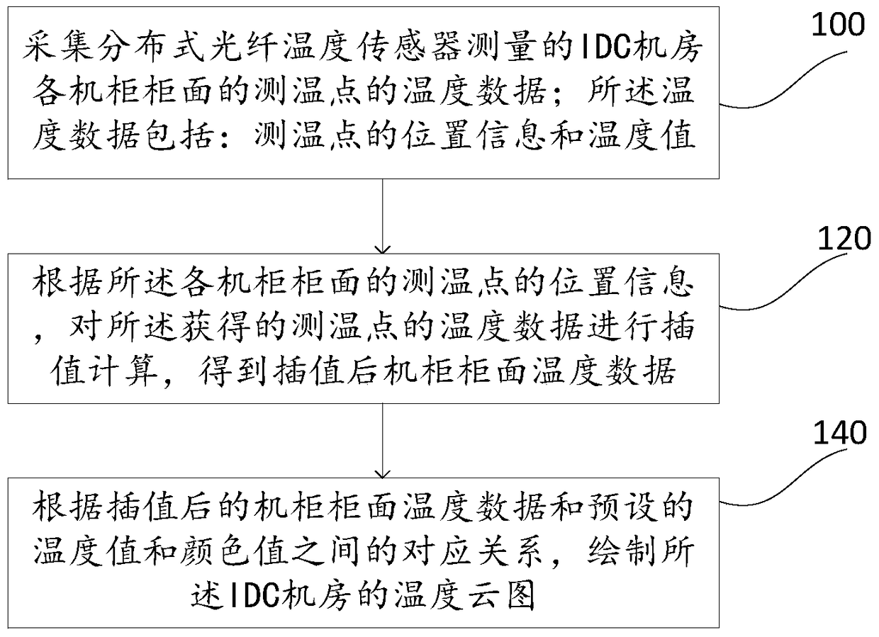
[0040] refer to figure 1 , figure 1 A schematic flowchart of a method for monitoring the temperature of an IDC machine room based on distributed optical fiber temperature measurement according to an embodiment of the present application is shown.

[0041] Step 100, collect the temperature data of the temperature measurement points on the surface of each cabinet in the IDC equipment room measured by the distributed optical fiber temperature sensor (DTS); the temperature data includes: the position information and the temperature value of the temperature measurement points.

[0042]Step 120, according to the position information of the temperature measuring points on the surface of each cabinet, perform i...


PUM


Abstract

This application provides a temperature monitoring method for an IDC computer room based on distributed optical fiber temperature measurement, which belongs to the field of monitoring technology and is used to solve the problem that the temperature monitoring method in the prior art cannot quickly and real-time display the temperature cloud map of the cabinet. The method includes: Collect the temperature data of the temperature measurement points on the cabinet surfaces of the IDC machine room measured by the distributed optical fiber temperature sensor; the temperature data includes: the position information and the temperature value of the temperature measurement points; Position information, performing interpolation calculation on the obtained temperature data of the temperature measuring point to obtain interpolated cabinet surface temperature data; according to the correspondence between the interpolated cabinet surface temperature data and the preset temperature value and color value to draw a temperature cloud map of the IDC computer room. The method is simple in calculation and has a small amount of calculation, and can draw a cloud map of the cabinet temperature of the IDC computer room in real time, effectively realizing the real-time temperature monitoring of the IDC computer room.

Description

technical field [0001] The present application relates to the field of monitoring technology, in particular to a temperature monitoring method and system for an IDC computer room based on distributed optical fiber temperature measurement. Background technique [0002] Our country is in an era of high-speed information exchange and dissemination, and the information network has been closely integrated with our daily work, life and study. As an important place for information processing and exchange, the location of the Internet Data Center (IDC) is particularly important. The computer room is generally equipped with many switches, storage machines, backup power supplies, refrigeration equipment, fire-fighting equipment, etc. These electronic devices heat up quickly, and the temperature of the computer room may rise beyond the normal temperature of the equipment in a short period of time. In addition, if the equipment in the computer room is short-circuited, overloaded, or th...

Claims


Application Information

Patent Timeline
Patent Type & Authority Patents(China)
IPC IPC(8): G01K11/32G01K1/02G01K1/024G01K11/324
CPCG16Z99/00G01K1/024G01K11/32G06F11/3058G06F11/3006G06F11/3044
Inventor 杨睿李小彦苗守功
Owner BEIJING AEROSPACE YILIAN TECH DEV
Why Eureka
Try Eureka