

Speed anisotropic microseismic monitoring positioning method, microseismic monitoring positioning terminal and microseismic monitoring positioning system
A technology for microseismic monitoring and positioning terminal, applied in the field of seismic positioning, can solve the problems of low accuracy, difficulty in realizing mine seismic monitoring and positioning calculation, etc., and achieve the effects of improving accuracy, reasonable structure design, and simple structure design.
- Summary
- Abstract
- Description
- Claims
- Application Information
AI Technical Summary
Problems solved by technology
Method used
Image

Examples
Embodiment Construction
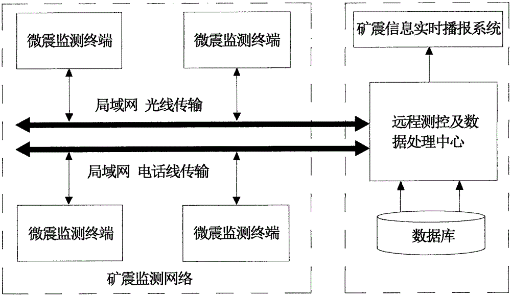
[0037] Such as figure 1 As shown, the velocity anisotropic microseismic monitoring and positioning method of the present invention is specifically to arrange several microseismic monitoring and positioning terminals on the ground and underground of the mining area through reasonable site selection to form a three-dimensional mine seismic monitoring network within the scope of the entire mining area; The monitoring and positioning terminal analyzes the frequency and amplitude characteristics of the vibration wave, and automatically identifies the mine shock wave; each monitoring sub-station transmits the monitored waveform data of the mine shock signal and its pre-analysis results to the remote measurement and control through the optical fiber network or the telephone network. And the data processing center, the remote measurement and control and data processing center receives the real-time data sent by the monitoring sub-station and performs secondary processing and analysis, ...
PUM
 Abstract
Description
Claims
Application Information