
Aircraft structure with solar energy capture capacity

An aircraft and photovoltaic technology, applied in the field of aircraft structure, can solve the problems of increased complexity of installation and maintenance of cable bundles, high energy consumption, and complex implementation, so as to reduce the number and time required for installation and inspection operations, and reduce power wiring , The effect of simplifying the cycle of maintenance

Inactive Publication Date: 2016-03-09
EUROPEAN AERONAUTIC DEFENCE & SPACE CO EADS FRANCE +1
View PDF6 Cites 3 Cited by
  • Summary
  • Abstract
  • Description
  • Claims
  • Application Information

AI Technical Summary

Problems solved by technology

[0007] Such a network of cable harnesses is obviously a disadvantage for the aircraft, both in terms of cost and weight
[0008] In addition, the arrangement of such a network of cable bundles presents the disadvantage of complex implementation, increased complexity in the operation of installing and maintaining these cable bundles
[0009] Also, since there are a relatively large number of these systems and they consume a lot of energy, the power supply must provide a lot of power, which is also a disadvantage in terms of cost and weight

Method used


Image

  • Aircraft structure with solar energy capture capacity
  • Aircraft structure with solar energy capture capacity
  • Aircraft structure with solar energy capture capacity

Examples


Embodiment Construction

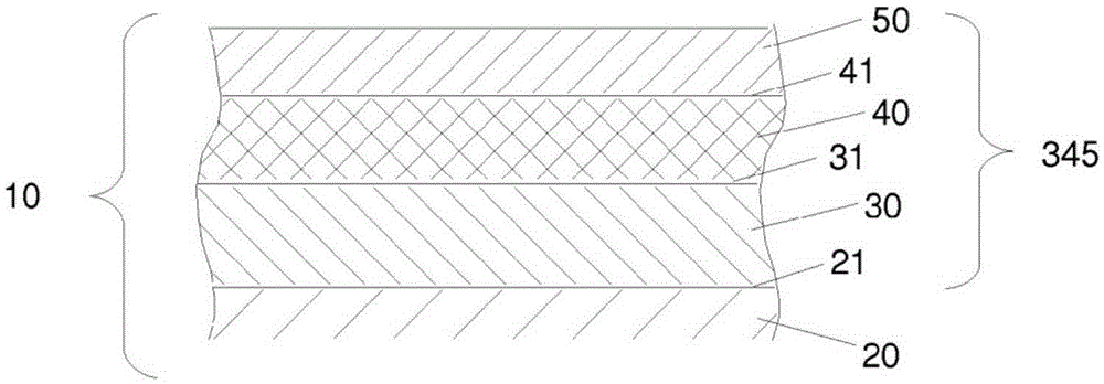
[0074] exist figure 1 An exemplary aircraft structure 10 according to the present invention is schematically shown in . figure 1 A partially flat aircraft structure is shown by way of example and does not limit the invention in any way.

[0075] exist figure 1 In , the relative thicknesses of the different layers of the aircraft structure have been chosen by way of example, and to clearly illustrate each layer, these relative thicknesses should not be considered in any way limiting or even representative of an actual multilayer assembly.

[0076] The aircraft structure 10 according to the invention is made of composite material and mainly comprises a structural part 20 comprising mineral or organic fibers held in a hard organic resin.

[0077] For example, such structural components 20 include fiberglass, aramid (Kevlar, ) fiber or carbon fiber (woven or unidirectional) stack.

[0078] The aircraft structure described is, for example, a fuselage and this choice does no...


PUM


Abstract

The invention relates to an aircraft structure (10), in particular the fuselage, nacelles or wings, comprising, over all or part of an outer surface (21) that may undergo lightning impacts, a layer of flexible polymer (30), a photovoltaic film (40) and a protective layer (50) protecting said photovoltaic film. This aircraft structure primarily has a solar energy capture capacity making it possible to meet the needs of an aircraft as well as an ability to protect against the effects of lightning.

Description

technical field [0001] The invention relates to an energy supply for aircraft. More specifically, the present invention relates to an aircraft structure with solar energy harvesting capabilities. [0002] The present invention offers particular advantages for aircraft structures made of composite materials. Background technique [0003] Current aircraft include embedded power sources intended to generate electrical power onboard that enables the supply of power to the different systems that consume it, whether on the ground or in flight. [0004] These systems are generally remote from each other and from the power source, distributed throughout the aircraft, from the cockpit through the wings to the tail of the aircraft. [0005] In systems that require power supply remote from the power source, there are, by way of illustrative example, strobe lights located at the end of the wing. [0006] In order to reach the system and provide power to each individual in the system,...

Claims


Application Information

Patent Timeline
Patent Type & Authority Applications(China)
IPC IPC(8): B64D33/00B64D41/00H01L31/048H01L31/0445
CPCH01L31/048H01L31/0445Y02E10/50B64D33/00Y02T50/50B64U50/31B64D27/353H01L31/049H01L31/03926H01L31/1876
Inventor 贝特朗·里夫吉勒斯·佩雷斯阿兰·波特
Owner EUROPEAN AERONAUTIC DEFENCE & SPACE CO EADS FRANCE
Learn More