
Scanning method and radio-frequency power calibration method and device of magnetic resonance imaging system

A technology of magnetic resonance imaging and calibration method, applied in magnetic resonance measurement, measurement device, measurement of magnetic variables, etc., can solve the problems of reducing the signal-to-noise ratio of the image, unable to obtain better imaging quality, and long scanning time, and achieve accurate calibration Structure, fast and efficient calibration, narrowing effect

Active Publication Date: 2016-03-16
NEUSOFT MEDICAL SYST CO LTD
View PDF9 Cites 15 Cited by
  • Summary
  • Abstract
  • Description
  • Claims
  • Application Information

AI Technical Summary

Problems solved by technology

[0006] This calibration method needs to traverse a range of pulse amplitudes during the process, and the scan time is relatively long, usually 30s or more. Usually, it can only be calibrated during the calibration of the entire system. After calibration, the flip angle and radio frequency can be obtained during calibration. The corresponding relationship of pulse amplitude is to determine the radio frequency pulse amplitude for different scanning subjects. However, there are individual differences in different subjects, and the radio frequency pulse amplitude determined for all subjects by only one calibration is not accurate enough, and then It will reduce the signal-to-noise ratio of the image and cannot obtain better image quality

Method used


Image

  • Scanning method and radio-frequency power calibration method and device of magnetic resonance imaging system
  • Scanning method and radio-frequency power calibration method and device of magnetic resonance imaging system
  • Scanning method and radio-frequency power calibration method and device of magnetic resonance imaging system

Examples


Embodiment Construction

[0044] As described in the background technology, in the magnetic resonance imaging system, in order to obtain the magnetic resonance imaging information, it is necessary to apply a radio frequency excitation field, so that the net magnetic moment formed by the spin proton is at a certain flip angle. The RF system in the system provides. Generally, a radio frequency system in an MRI system usually includes a radio frequency transmitting unit, a radio frequency amplifier, a radio frequency transmitting coil, a radio frequency receiving coil, and a radio frequency receiving unit. Among them, for a scanning process, the radio frequency transmitting unit outputs a radio frequency pulse signal with a specific center frequency, bandwidth, amplitude and phase, the radio frequency amplifier amplifies the power of the radio frequency pulse signal output by the radio frequency transmitting unit, and the radio frequency transmitting coil receives the radio frequency pulse signal output by...


PUM


Abstract

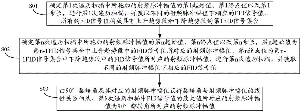
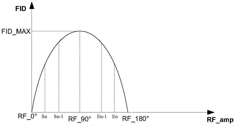
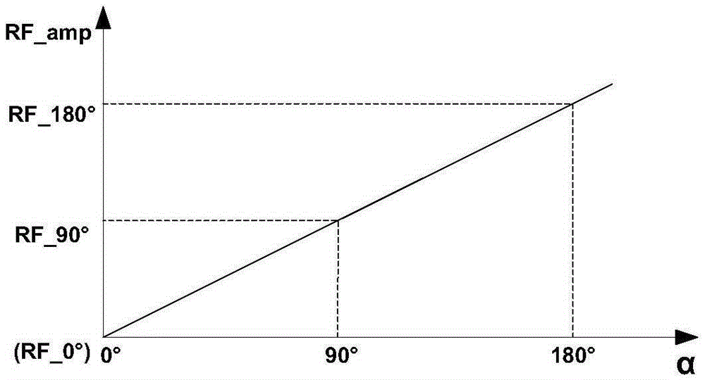
The embodiment of the invention discloses a radio-frequency power calibration method of a magnetic resonance imaging system. In the method, radio-frequency pulse amplitudes progressively increasing in a larger step length mode are first selected to undergo traversal scanning during traversal, FID signal values corresponding to the different radio-frequency pulse amplitudes are obtained, the step length is constantly decreased during traversal scanning of the next time, a traversal scanning range is constantly narrowed by determining an initial value and an end point value for traversal again, accordingly the radio-frequency pulse amplitudes corresponding to 90-degree turning angles are quickly and accurately determined, and further a linear relation curve about the turning angles and the radio-frequency pulse amplitudes is obtained according to the 90-degree turning angles and the radio-frequency pulse amplitudes. The radio-frequency power calibration method can quickly and effectively calibrate the radio-frequency power, conveniently provides more accurate calibration structures for different subjects and further obtains better imaging quality.

Description

technical field [0001] The invention relates to the field of magnetic resonance imaging systems, in particular to a scanning method for a magnetic resonance imaging system, a radio frequency power calibration method and a device. Background technique [0002] The magnetic resonance imaging system (MRI) uses the combination of pulsed gradient magnetic field and pulsed radio frequency (RF) magnetic field to obtain the magnetic resonance imaging information of the spin protons of the imaging sample placed in the static magnetic field in the designated imaging area. A polarized spin proton placed in a static magnetic field has a net magnetic moment, and the direction of the magnetic moment is the direction of the spin axis of the proton. The direction of the proton spin axis always tends to be along the external static magnetic field , the individual spin protons always precess around the static magnetic field axis at the Larmor frequency of the magnetic spin ratio multiplied ...

Claims


Application Information

Patent Timeline
IPC IPC(8): A61B5/055
CPCG01R33/586G01R33/36G01R33/58
Inventor 史建华胡红兵李海泉吴林王宏伟孙容王艳左红
Owner NEUSOFT MEDICAL SYST CO LTD
Learn More