Method and device for calibrating structural parameters of machine tool and machine tool control system

A structural and parametric technology, applied in the field of machine tools, can solve the problems of high instrument cost, time-consuming and laborious, complex structure, etc.

Active Publication Date: 2022-04-29
上海柏楚电子科技股份有限公司
View PDF0 Cites 0 Cited by
  • Summary
  • Abstract
  • Description
  • Claims
  • Application Information

AI Technical Summary

Problems solved by technology

However, the CNC system using the ballbar is expensive, and the operator needs to be familiar with the relevant programming and the use of the ballbar, and this method is only suitable for machine tools with hardware tools, which has certain limitations
Using a laser interferometer for calibration, although the measurement accuracy is high, the equipment cost is too expensive, and the operation is extremely cumbersome and complicated
Calibrating with a dial indicator requires a lot of manpower, which is time-consuming and labor-intensive
There is also a calibration method using a CCD (charge-coupled device) camera for laser detection, but this method requires the machine tool to have a very high installation verticality. However, in the actual installation process of the machine tool, the cost of ensuring the verticality of the installation is extremely high, and the verticality The degree itself, like other structural parameters, will deviate from the preset value due to the vibration caused by processing
In addition, the above-mentioned calibration method using a CCD camera for laser detection needs to install a rotating table, which has a complicated structure
Moreover, most of the existing calibration methods can only correct the structural parameters related to the length, but the structural parameters of the machine tool also include parameters related to the rotation angle (for example, the verticality mentioned above), so such a calibration method Can't really achieve accurate calibration

Method used


Image

  • Method and device for calibrating structural parameters of machine tool and machine tool control system
  • Method and device for calibrating structural parameters of machine tool and machine tool control system
  • Method and device for calibrating structural parameters of machine tool and machine tool control system

Examples


Embodiment Construction

[0044] The present invention will be further described below in conjunction with specific embodiment and accompanying drawing, set forth more details in the following description in order to fully understand the present invention, but the present invention can obviously be implemented in many other ways different from this description Those skilled in the art can make similar promotions and deductions based on actual application situations without violating the spirit of the present invention. Therefore, the content of this specific embodiment should not limit the protection scope of the present invention.

[0045] Unless otherwise defined, the technical terms or scientific terms used in the claims and the description shall have the ordinary meanings understood by those skilled in the technical field to which the present invention belongs. "First", "second" and similar words used in the description and claims of the present application do not indicate any sequence, quantity or ...


PUM


Abstract

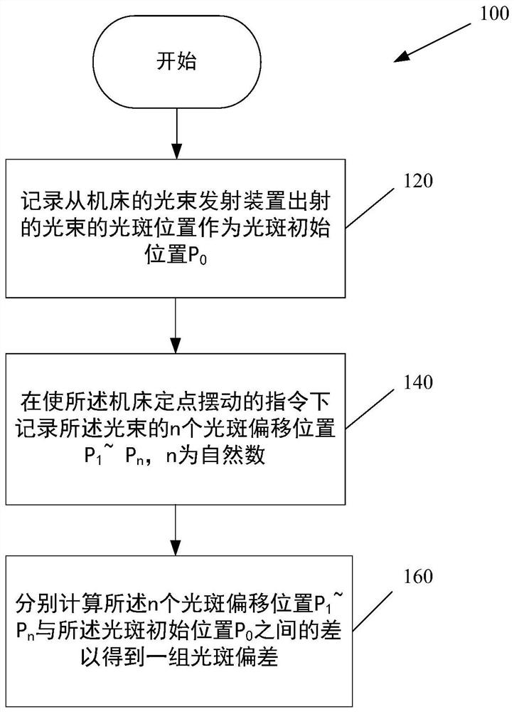
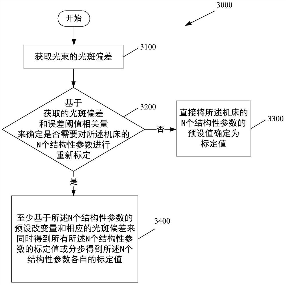
The present invention relates to a method, a device and a machine tool control system for calibrating structural parameters of a machine tool, and also relates to a method for obtaining light spot deviation in calibrating the structural parameters of a machine tool. The method for calibrating the structural parameters of the machine tool includes: using the above-mentioned spot deviation sampling method to obtain the spot deviation of the beam, and determining whether to recalibrate the structural parameters of the machine tool based on the spot deviation and the error threshold related quantity ; If recalibration is not required, then directly determine the preset value of the structural parameter of the machine tool as the calibration value; if recalibration is required, at least obtain all The calibration value of the structural parameters or step by step to obtain the calibration value of each structural parameter.

Description

technical field [0001] The present invention relates to the field of machine tools, more specifically to a method and device for calibrating structural parameters of machine tools and a corresponding machine tool control system. Background technique [0002] Machine tool processing plays a pivotal role in modern machinery manufacturing, but any parts that require high precision and fine surface roughness generally require final processing on machine tools. There are many types of machine tools, but no matter what kind of machine tool, the accuracy of its structural parameters (such as the length of each rotating axis, installation verticality, etc.) will eventually affect the actual machining accuracy. [0003] In the process of installing the actual machine tool according to its design drawings, due to the existence of tolerances and installation errors, its actual structural parameters will inevitably deviate from the originally designed structural parameters. Similarly, ...

Claims


Application Information

Patent Timeline
Patent Type & Authority Patents(China)
IPC IPC(8): B23Q15/00B23Q17/24
CPCB23Q15/00B23Q17/24
Inventor 谢淼徐力宇罗一尧
Owner 上海柏楚电子科技股份有限公司
Why Eureka
Try Eureka