Essential oil thermocatalysis device

A thermal catalysis, essential oil technology, applied in the direction of gasification substances, atomized substances, chemical instruments and methods, etc., can solve the problems of slow volatilization rate of essential oils, slow volatilization rate, large heat loss, etc., and achieve small heat loss and soft aroma. Natural, temperature-controlled effects

Inactive Publication Date: 2016-03-16
胡积献 +1
View PDF5 Cites 3 Cited by
  • Summary
  • Abstract
  • Description
  • Claims
  • Application Information

AI Technical Summary

Problems solved by technology

This type of literature can refer to the Chinese utility model patent "Aroma Diffuser" (the authorized announcement number is CN2850619Y) whose patent number is ZL200520120971.6, but because the cotton core is prone to blockage during use, the volatilization rate of essential oil is slow; in order to overcome the above-mentioned For the defect of slow volatilization rate of essential oil, the technical scheme of replacing the cotton core with a mandrel made of hard material makes the mandrel protrude from the end face of the essential oil compartment and is heated by a constant temperature of the electric heating component to volatilize the essential oil in the essential oil compartment to achieve the maximum volatilization of essential oil Effect, such as a Chinese utility model patent "Essence Oil Thermal Catalytic Device" (authorized announcement number is CN202777177U) with a patent number of ZL201220102282. The upper electrode piece, the lower electrode piece, the metal shrapnel, two PTC thermistors and the heat conduction ring are composed. The heat conduction ring is set on the through hole in the shell, and the upper electrode piece and the lower electrode piece clamp the PTC thermistor through the metal shrapnel. PCT thermistors are symmetrically arranged on both sides of the heat conduction ring, and an internal thread for installing an essential oil container is provided at the bottom of the device. One end of a microporous ceramic core rod is set in the essential oil container, and the other end extends into the electric heater. In the through hole of the component, the essential oil can be thermally diffused through the microporous ceramic core rod from the inside to the outside through the electric heating component. The disadvantage is that the heat conducting ring is located on both sides of the microporous ceramic core rod and there is a gap between them. In this way, when the mandrel is heated through the side, the thermal conductivity between the electric heating component and the mandrel will be poor due to the air between the two, and the heat loss will be large, which will slow down the volatilization rate of the essential oil, and eventually lead to the use of the aromatherapy machine or aromatherapy device. The power is large, and the use effect is not ideal, which will significantly reduce the service life of the aromatherapy machine or aromatherapy device

Method used


Image

  • Essential oil thermocatalysis device
  • Essential oil thermocatalysis device
  • Essential oil thermocatalysis device

Examples


Embodiment 1

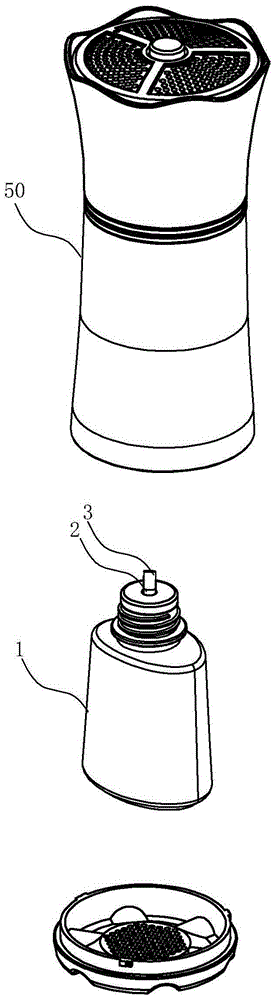
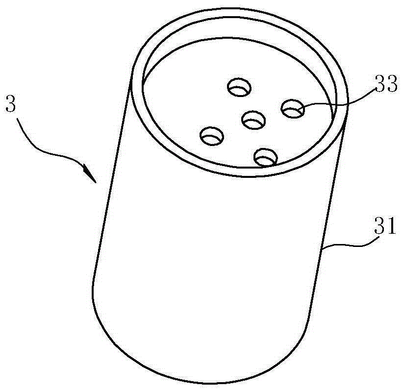
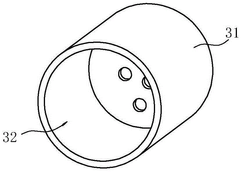
[0026] Such as Figure 1~4As shown, the essential oil thermocatalytic device includes an essential oil bottle 1 for storing essential oil placed in the housing 50 of the air freshener and a catalytic core head 3 installed on the essential oil bottle 1 to convert the essential oil from liquid to gaseous state and distribute it outward , the catalytic core head 3 includes a cover, the cover is surrounded by a convex wall 31 to form a cavity 32 capable of accommodating the mandrel 2 , and the cover is provided with a plurality of through holes 33 relative to the end of the mandrel 2 . In the present embodiment, the catalytic core head 3 is cylindrical to ensure that all the heat of the catalytic core head 3 is used to heat the mandrel 2. The catalytic core head 3 replaces the traditional core head with microporous ceramic material. The core head with microporous ceramic material heats the PTC thermistor by electrifying the electrode, and then continuously lifts the essential oil ...

Embodiment 2

[0030] The difference from Example 1 is that the end of the mandrel 2 is closely attached to the ultrasonic atomizing sheet 4, and the controller on the circuit control board is electrically connected to the atomizing sheet 4 and is used to drive the atomizing sheet 4 to vibrate, and catalyzes when installed. The core head 3 is arranged on the top of the mandrel 2 atomizing sheet 4 with a distance of 1 mm, wherein the catalytic core head 3 can be fixed with a fixing device arranged in the housing 50 of the air freshener, and the specific method is not to be unfolded here. And the end of the mandrel 2 is closely attached to the atomizing sheet 4, and the outlet aperture 41 of the ultrasonic atomizing sheet 4 is 4um. Through the high-frequency resonance of the atomizing sheet, the structure of the essential oil is broken up to produce a natural and elegant water mist , the atomized essential oil is sprayed into the catalytic core head for high-temperature catalysis, and finally e...


PUM

PropertyMeasurementUnit
pore sizeaaaaaaaaaa

Abstract

The invention relates to an essential oil thermocatalysis device. The essential oil thermocatalysis device comprises an essential oil bottle used for storing essential oil, and a core rod; the upper end of the core rod is stretched out from the opening of the essential oil bottle, and the lower end of the core rod is inserted into the essential oil bottle; the essential oil thermocatalysis device also comprises a catalytic burner used for transforming essential oil in the essential oil bottle from liquid states into gas states and realizing dispersing of essential oil; the catalytic burner comprises a cover body; the periphery of the cover body is provided with an accommodation chamber formed via encircling of a convex wall; and the end part of the cover body is provided with at least one through hole. Compared with the prior art, the advantages of the essential oil thermocatalysis device are that: the catalytic burner is provided with the accommodation chamber capable of accommodating the core rod, the accommodation chamber is capable of ensuring that all heat energy of the catalytic burner is used for heating the core rod, heat energy loss is low, essential oil volatilization rate is increased, and temperature can be increased to 100 DEG C quickly in 30s to 1min.

Description

technical field [0001] The invention relates to an essential oil catalytic device used in an aroma diffuser, in particular to an essential oil thermal catalytic device. Background technique [0002] Aromatherapy essential oil is a kind of fragrant and volatile plant essential oil made by extracting specific kinds of plants through special methods. Plant essential oil is the essence of extracted plant ingredients. It not only has a pleasant aromatic smell, but also has the characteristics of high volatility, small molecules, and can be quickly absorbed by the human body. It also has extremely high medicinal value, whether it is in maintenance It has a certain effect on skin, balancing internal functions and alleviating unfavorable mental emotions. [0003] Aromatherapy products have been in the market for more than ten years. Although the concept is accepted by the general public and the products are also loved by many people, there are still some deficiencies in the structu...

Claims


Application Information

Patent Timeline
Patent Type & Authority Applications(China)
IPC IPC(8): A61L9/03A61L9/14A61L9/22B01D53/76B01D53/72B01D53/62
CPCA61L9/037A61L9/14A61L9/22B01D53/62B01D53/72B01D53/76B01D2257/502B01D2257/70B01D2257/91B01D2259/10B01D2259/122B01D2259/4508
Inventor 胡积献
Owner 胡积献
Why Eureka
Try Eureka