Cutting machine workbench

A technology of workbench and cutting machine, applied in the direction of manufacturing tools, metal processing equipment, welding equipment, etc., can solve the problems of wasting manpower time, loss of top cover, endangering human health, etc., to speed up cutting efficiency, improve efficiency, and protect the environment Effect

Inactive Publication Date: 2016-03-16
湖北可腾机械有限公司
View PDF0 Cites 3 Cited by
  • Summary
  • Abstract
  • Description
  • Claims
  • Application Information

AI Technical Summary

Problems solved by technology

In the prior art, in the metal material cutting technology for valves, a variety of harmful gases and smoke will be produced during the laser cutting process, and the commonly used laser cutting machine worker's workbench is exposed to the outside, although the workbench There is a dust collector and a slag discharger at the bottom to extract the smoke and dust generated during processing, but there is no effective protection device above the cutting table, and some harmful gases and smoke will still leak into the air from above the table, endangering human beings In addition, during the cutting process, if there is no protective device, it is not convenient for the operator to come close to watch the cutting effect. Some laser cutting machines have a top cover on the top of the table, but it is necessary to open and close the top cover when transporting the workpiece, which wastes Manpower time, but also cause loss of top cover, waste of cost

Method used


Image

  • Cutting machine workbench

Examples


Embodiment Construction

[0016] The principles and features of the present invention are described below in conjunction with the accompanying drawings, and the examples given are only used to explain the present invention, and are not intended to limit the scope of the present invention.

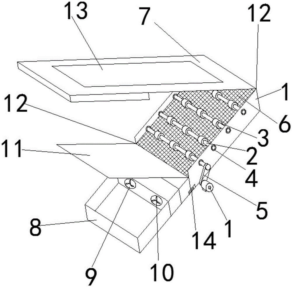
[0017] combined with figure 1 , a workbench of a cutting machine according to the present invention, comprising a workbench 1, the workbench 1 is a square box, the interior is hollow, the top wall and one of the side walls are opened, and several conveyors are arranged at the same height in the workbench 1. frame, the conveying frame includes a rotating shaft 2, and several rotating rollers 3 are evenly arranged on the rotating shaft 2. In this embodiment, three rotating rollers 3 are arranged on the rotating shaft 2, and four conveying frames are arranged at the same height in the workbench 1 , the conveying racks are all connected through the rotating shaft 2 and the bearing 4 fixedly arranged on the side wall of ...


PUM


Abstract

The invention discloses a cutting machine workbench, and relates to the technical field of cutting machine accessories. The cutting machine workbench comprises a workbench body, the workbench body is a square box and is hollow, the top wall and one side wall of the working table are open, and a plurality of conveying supports are further arranged at the positions, at the same height, in the workbench body; each conveying support comprises a rotating shaft which is evenly provided with a plurality of rotating rollers, the conveying supports are in fit connection with bearings fixedly arranged on the side walls of the workbench body through the rotating shafts, and a rotating support close to the lateral wall with the opening is connected with a motor outside the workbench body; a net-shaped material support is further arranged at the diameter height position of the rotating roller inside the workbench body, a movable cover plate is arranged on the workbench body, a material receiving table is further connected to the exterior of the workbench body, and a discharging plate is erected on the top of the material receiving table; and a dust sucking channel is further formed in the material receiving channel, and a draught fan is arranged in the dust sucking channel. The cutting machine workbench is simple in structure and convenient to operate, the working efficiency is improved, dust generated during cutting can be effectively collected, air splashing is prevented, and the working state is conveniently observed.

Description

technical field [0001] The invention relates to the technical field of cutting machine accessories, in particular to a cutting machine workbench. Background technique [0002] Laser cutting machines have been widely used in all walks of life. They can cut a variety of metals and non-metals, and can also be engraved. They have the advantages of high cutting precision, good stability, good cutting section quality, fast, simple operation, and high degree of automation. Laser cutting machine includes: laser, beam transmission components, workbench, microcomputer numerical control device, chiller, exhaust dust collector and slag discharger, etc. In the prior art, in the metal material cutting technology for valves, a variety of harmful gases and smoke will be produced during the laser cutting process, and the commonly used laser cutting machine worker's workbench is exposed to the outside, although the workbench There is a dust collector and a slag discharger at the bottom to ex...

Claims


Application Information

Patent Timeline
Patent Type & Authority Applications(China)
IPC IPC(8): B23K26/70B23K26/16
CPCB23K26/16
Inventor 王昌锐
Owner 湖北可腾机械有限公司
Why Eureka
Try Eureka