Wafer mounting and lifting conveying device of graphite boat

A transmission device and graphite boat technology, which is applied to conveyors, mechanical conveyors, transportation and packaging, etc., can solve the problems that it is difficult to ensure that the graphite boat is placed on the translation support, the graphite boat is large in size, and labor-intensive. Chip transmission problem, simple device structure and high degree of automation

Active Publication Date: 2016-03-16
SHENGZHOU SIGMA TECH
View PDF13 Cites 8 Cited by
  • Summary
  • Abstract
  • Description
  • Claims
  • Application Information

AI Technical Summary

Problems solved by technology

Before the silicon wafer in the graphite boat is processed in the next process, the graphite boat needs to be placed horizontally on the upper side of the translation support, so that the graphite boat can be transported and processed horizontally and smoothly. Traditionally, the graphite boat is manually transported to the translation On the upper side of the bracket, due to the large volume and heavy weight of the graphite boat, the labor intensity of the workers in the process of moving the graphite boat is relatively high. It is difficult for the graphite boat lifting device in the prior art to ensure that the graphite boat Both sides are lifted and lowered synchronously, causing the graphite boat to tilt during the lifting process, and during the translation process of the graphite boat, it is difficult for both sides of the graphite boat to translate synchronously, making it difficult to ensure that the graphite boat is accurately placed on the translation support, which reduces the graphite boat. The processing quality of the silicon wafer back-end process reduces the work efficiency and quality, and it is difficult to meet the needs of production
In addition, the graphite boat loading work in the prior art still requires manual loading work, and workers need to move around the workbench 180 degrees to load the wafers, resulting in high work intensity, long time consumption and low work efficiency for workers

Method used


Image

  • Wafer mounting and lifting conveying device of graphite boat
  • Wafer mounting and lifting conveying device of graphite boat
  • Wafer mounting and lifting conveying device of graphite boat

Examples


Embodiment Construction

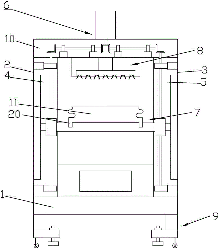
[0028] Such as Figure 1 to Figure 5 As shown, a loading and unloading transmission device for a graphite boat includes a frame 1 on which a lifting frame is arranged, and the lifting frame includes a left lifting frame 2 and a right lifting frame 3. Left lifting frame 2 is installed in the left end of frame 1, and right lifting frame 3 is installed in the right-hand end of frame 1, and left lifting frame 2 is provided with left lifting groove 4, and right lifting frame 3 is provided with right lifting groove 5.

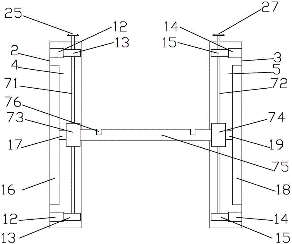
[0029] There is a lifting mechanism in the lift frame, and the lifting mechanism 7 includes a lifting screw mandrel and a lifting transmission seat, and the lifting screw mandrel includes a left lifting screw mandrel 71 and a right lifting screw mandrel 72, and the left lifting screw mandrel 71 and the right lifting screw mandrel 72 are all vertically arranged , The lifting transmission seat comprises a left lifting transmission seat 73 and a right lifting transmissi...


PUM


Abstract

The invention discloses a wafer mounting and lifting conveying device of a graphite boat. The wafer mounting and lifting conveying device comprises a rack. A lifting frame is arranged on the rack and comprises a left lifting frame body and a right lifting frame body. A lifting mechanism is arranged in the lifting frame and comprises lifting lead screws and lifting transmission seats. The lifting lead screws comprise the left lifting lead screw and the right lifting lead screw. The left lifting lead screw and the right lifting lead screw are both arranged vertically. The lifting transmission seats comprise the left lifting transmission seat and the right lifting transmission seat. The left lifting transmission seat is arranged on the left lifting lead screw, and the right lifting transmission seat is arranged on the right lifting lead screw. A lifting plate is connected between the left lifting transmission seat and the right lifting transmission seat and provided with the graphite boat. A supporting table is arranged between the left lifting frame body and the right lifting frame body and provided with a lifting transmission mechanism, and the lifting transmission mechanism is connected with the lifting mechanism. The device is simple in structure, scientific, convenient to use, high in pertinence and automation degree, good in wafer mounting effect and high in conveying efficiency, and the wafer mounting conveying problem of the graphite boat is solved well.

Description

technical field [0001] The invention relates to a sheet loading, lifting and conveying device for a graphite boat. Background technique [0002] In the production process of crystalline silicon solar cells, it is necessary to uniformly put the silicon wafers that have undergone texturing, high-temperature diffusion and etching into the graphite boat one by one, and then transport the graphite boat smoothly, so that the silicon in the graphite boat The sheet can be processed in the next process. Before the silicon wafer in the graphite boat is processed in the next process, the graphite boat needs to be placed horizontally on the upper side of the translation support, so that the graphite boat can be transported and processed horizontally and smoothly. Traditionally, the graphite boat is manually transported to the translation On the upper side of the bracket, due to the large volume and heavy weight of the graphite boat, the labor intensity of the workers in the process of ...

Claims


Application Information

Patent Timeline
Patent Type & Authority Applications(China)
IPC IPC(8): B65G35/00
CPCB65G35/00B65G2201/02
Inventor 马建军
Owner SHENGZHOU SIGMA TECH
Why Eureka
Try Eureka