Textile rack

A textile frame and motor technology, applied in the textile field, can solve the problems of occupation, adjustment of textile speed, large working space, etc.

Inactive Publication Date: 2016-03-16
WUHU KANGDAOER TEXTILE SCI
View PDF0 Cites 4 Cited by
  • Summary
  • Abstract
  • Description
  • Claims
  • Application Information

AI Technical Summary

Problems solved by technology

However, the weaving frame has low working efficiency, it is difficult to adjust the weaving speed according to actual needs, and it will take up a large working space

Method used


Image

  • Textile rack
  • Textile rack

Examples


Embodiment Construction

[0022] Specific embodiments of the present invention will be described in detail below in conjunction with the accompanying drawings. It should be understood that the specific embodiments described here are only used to illustrate and explain the present invention, and are not intended to limit the present invention.

[0023] In the present invention, in the absence of a contrary description, the orientation words included in the term such as "top and bottom" only represent the orientation of the term in the normal use state, or the common name understood by those skilled in the art, should not be construed as a limitation of this term.

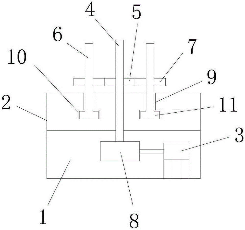
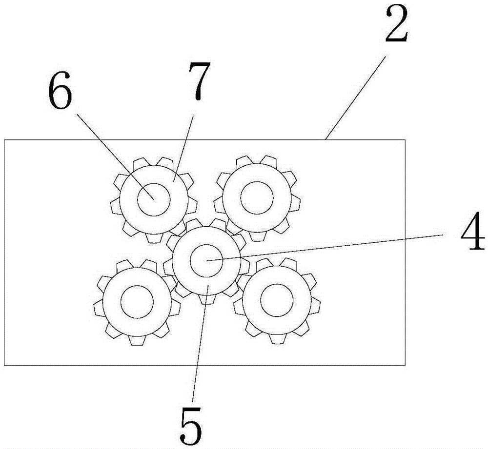
[0024] see figure 1 , the present invention provides a textile frame, which comprises a base 2 with a cavity 1, a motor 3, a main rotating shaft 4, a main rotating gear 5, a plurality of slave rotating shafts 6 and a slave rotating gear 7; wherein, The motor 3 is arranged in the base 2, and the rotating shaft 6 is vertically arranged on the...


PUM


Abstract

The invention discloses a textile rack. The textile rack comprises a base (2) with a cavity (1), a motor (3), a driving rotary shaft (4), a driving rotary gear (5), multiple driven rotary shafts (6) and multiple driven rotary gears (7), wherein the motor is arranged inside the base; the driven rotary shafts are vertically arranged on the top end surface of the base; one end of the driving rotary shaft is connected with a rotary shaft of the motor; the other end of the driving rotary shaft penetrates through the top end surface of the base and vertically outwards extends; the outer wall of the driving rotary shaft is sleeved with the driving rotary gear; the outer walls of the driven rotary shafts are sleeved with the driven rotary gears; teeth of the driven rotary gears can be engaged with teeth on the driving rotary gear. The textile rack is small in occupied space, and can increase the weaving speed and improve the textile production efficiency.

Description

technical field [0001] The invention relates to the technical field of textiles, in particular to a textile frame. Background technique [0002] A textile machine is a tool for processing raw materials such as thread, silk, and hemp into silk threads and then weaving them into cloth. There are many types of textile frames on the market, generally including a base and a frame. The frame is installed on the base. In the winding device, the output end of the driving device is connected with the winding device to drive the winding device to rotate. The textile frame is easy to use, simple to operate, and safe and reliable. However, the weaving frame has low working efficiency, it is difficult to adjust the weaving speed according to actual needs, and it takes up a large working space. Contents of the invention [0003] The object of the present invention is to provide a weaving frame, which occupies a small space, can speed up the weaving speed, and improves the efficiency of...

Claims


Application Information

Patent Timeline
Patent Type & Authority Applications(China)
IPC IPC(8): B65H49/18B65H54/40
CPCB65H49/18B65H54/40B65H2403/40
Inventor 桑国海
Owner WUHU KANGDAOER TEXTILE SCI
Why Eureka
Try Eureka