Magnetic negative stiffness damper

A negative stiffness and damper technology, applied in the direction of magnetic springs, springs/shock absorbers, mechanical equipment, etc., can solve problems such as complex sensor structures, and achieve simple and compact structures

Active Publication Date: 2016-03-16
THE HONG KONG POLYTECHNIC UNIV
View PDF4 Cites 26 Cited by
  • Summary
  • Abstract
  • Description
  • Claims
  • Application Information

AI Technical Summary

Problems solved by technology

[0007] The technical problem to be solved by the present invention is to provide a passive magnetic negative stiffness mechanism combined with negative stiffness and

Method used


Image

  • Magnetic negative stiffness damper
  • Magnetic negative stiffness damper
  • Magnetic negative stiffness damper

Examples


Example Embodiment

[0028] In order to make the objectives, technical solutions and advantages of the present invention clearer, the following further describes the present invention in detail with reference to the accompanying drawings and embodiments.
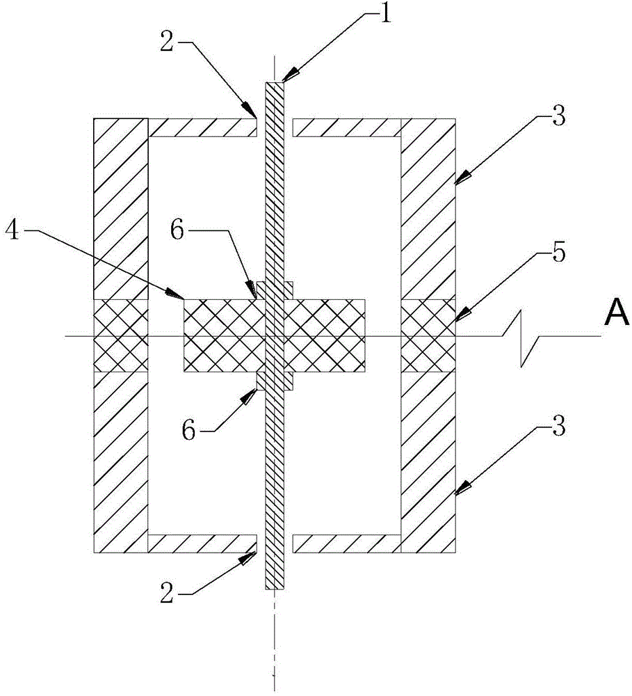
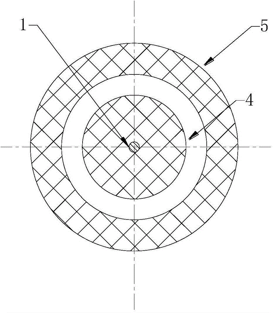
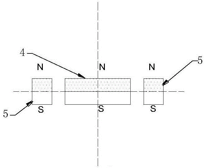
[0029] See Figure 1a with 1b These are respectively a vertical sectional view and a horizontal sectional view of the first embodiment of the magnetic negative stiffness damper according to the present invention. among them Figure 1a Is the cross-sectional view of the magnetic negative stiffness damper along the plane of the vertical longitudinal axis, Figure 1b for Figure 1a A cross-sectional view of the horizontal cross section at the middle edge A. Such as Figure 1a with 1b As shown, the magnetic negative-stiffness damper (MNSD) provided by this embodiment includes a mounting shaft 1, a sliding bearing 2, and a pair of magnets arranged along the axial direction of the conductive tube 3. The pair of magnets includes a first magnet 4 and a second ...


PUM


Abstract

The invention relates to a magnetic negative stiffness damper. The magnetic negative stiffness damper comprises a conductive pipe, an installation shaft, a sliding bearing and one or more pairs of magnets arranged in the axial direction of the conductive pipe. Each pair of magnets comprises the first magnet and the second magnet with the geometric centers located in the same horizontal positions in a balanced state. The first magnets are installed inside the conductive pipe through the installation shaft and are controlled by the sliding bearing to move in the axial direction. The second magnets are fixed to the conductive pipe. The axial magnetization directions of the first magnets and the second magnets are the same, and the negative stiffness function is formed through the relative movement of the first magnets and the second magnets. The conductive pipe is located in the position symmetrical with the two ends of the second magnets, and an electric eddy current damping function is formed through the relative movement of the first magnets and the conductive pipe. The magnetic negative stiffness damper integrates negative stiffness and electric eddy current damping, is simple and compact in structure and is capable of being widely applied to vibration control of construction, mechanical and aerospace structures.

Description

technical field [0001] The invention relates to the field of ultra-precise damping, and more specifically relates to a magnetic negative stiffness damper. Background technique [0002] Structural vibration control refers to the protection of the main structural system against strong vibrations caused by dynamic loads. Various passive, semi-active or active mode dampers have been proposed for damping structural vibrations, such as viscous fluid dampers, viscoelastic dampers, metallic yield dampers, friction dampers, tuned mass dampers, magnetic flow dampers, Variable (magnetorheology, MR) damper, variable orifice damper, variable friction damper and active mass drive. Some of them have been successfully applied in civil, mechanical and aerospace engineering. Active and semi-active control techniques tend to achieve better control than passive dampers. The Linear Quadratic Regulator (LQR) algorithm, commonly used as an optimal control theory for active dampers, can generate...

Claims


Application Information

Patent Timeline
IPC IPC(8): F16F6/00
Inventor 朱松晔石翔
Owner THE HONG KONG POLYTECHNIC UNIV
Why Eureka
Try Eureka