Dual-loop feedback constant-current source circuit

A constant current source and circuit technology, applied in the electronic field, can solve problems such as only at the milliampere level, limited improvement in stability, and greater impact, to achieve the effects of ensuring safety, improving stability, and improving safety

Inactive Publication Date: 2016-03-16
JILIN UNIV
View PDF5 Cites 20 Cited by
  • Summary
  • Abstract
  • Description
  • Claims
  • Application Information

AI Technical Summary

Problems solved by technology

Among these schemes, the first scheme is greatly affected by the device itself and has limited improvement in stability; the second scheme can effectively reduce the impact of changes in load resistance due to a large resistor connected in series in the load circuit. The influence of the output current, but due to the existence of a large resistance in the load circuit, the output current is very small when the power supply voltage is constant, generally only in the milliampere level, and most of the voltage is dropped on the large resistance. The efficiency is extremely low; the third scheme is the most effective way to improve current stability because of the automatic adju...

Method used


Image

  • Dual-loop feedback constant-current source circuit
  • Dual-loop feedback constant-current source circuit
  • Dual-loop feedback constant-current source circuit

Examples


Embodiment 1

[0035] Embodiment 1 Overall structure of the present invention

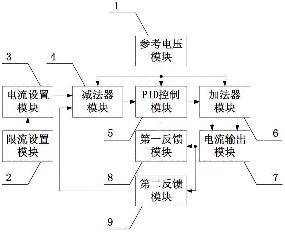
[0036] combine figure 1 The overall working principle of a double-loop feedback constant current source circuit of the present invention is described. A maximum control voltage is set by the current limiting setting module 1, and the current setting module 2 can output a control voltage between 0 and the maximum control voltage by using the sliding rheostat W2, and the second feedback module 9 samples the output current and converts it into a corresponding The above two voltages are differenced in the subtracter module 4, and the difference is sent to the PID module 5 for PID processing. The three voltage signals obtained are added by the adder module 6 and sent to the current output as the driving voltage The control input terminal of the module 7 is compared with the feedback voltage of the first feedback module 8, and the output current of the comparison result controls the current output module 7, and the re...

Embodiment 2

[0037] Embodiment 2 The reference voltage module 1 of the present invention

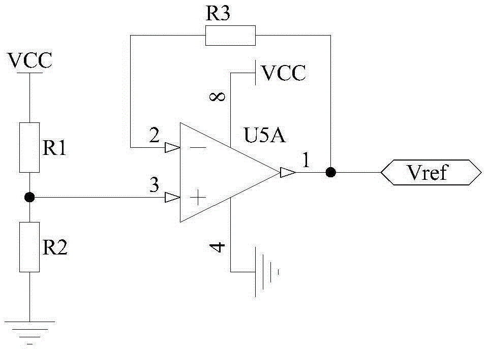
[0038] The principle circuit of the reference voltage module 1 of the present invention is as figure 2 As shown, one end of the resistor R1 is connected to the power supply VCC, the other end is connected to the non-inverting input terminal of the op amp U5A and one end of the resistor R2, the other end of the resistor R2 is grounded, the inverting input terminal of the op amp U5A is connected to one end of the resistor R3, and the resistor R3 The other end of the operational amplifier U5A is connected to the output terminal of the operational amplifier U5A, the positive power supply terminal of the operational amplifier U5A is connected to the power supply VCC, and the negative power supply terminal is grounded. The output terminal of the operational amplifier U5A is used as the output terminal of the reference voltage module 1, which is recorded as the port Vref.

[0039] Resistors R1 and R2 divid...

Embodiment 3

[0040] Embodiment 3 Current limiting setting module 2 of the present invention

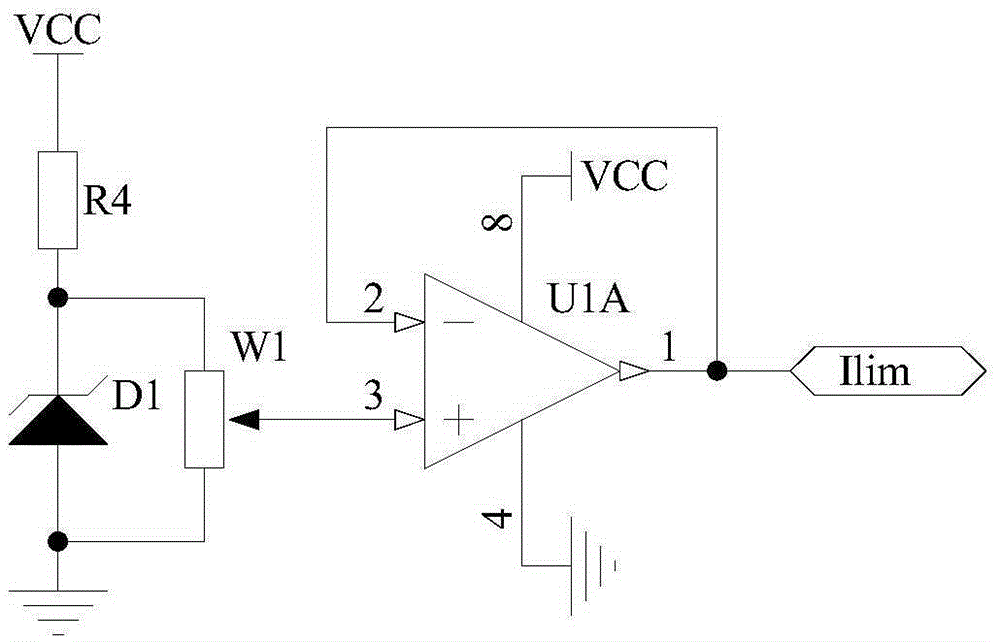
[0041] The principle circuit of the current limiting setting module 2 of the present invention is as image 3 As shown, one end of the resistor R4 is connected to the power supply VCC, the other end is connected to one end of the sliding rheostat W1 and the negative pole of the Zener diode D1, the other end of the sliding rheostat W1 and the positive pole of the Zener diode D1 are grounded, and the sliding end of the sliding rheostat W1 is connected to the operation The non-inverting input terminal of the amplifier U1A, the inverting input terminal of the operational amplifier U1A is connected to the output terminal of the operational amplifier U1A, the positive power supply terminal of the operational amplifier U1A is connected to the power supply VCC, the negative power supply terminal is grounded, and the output terminal of the operational amplifier U1A is used as a current limit setting module ...


PUM

PropertyMeasurementUnit
Capacitanceaaaaaaaaaa

Abstract

The invention discloses a dual-loop feedback constant-current source circuit and belongs to the technical field of electronic technology. The dual-loop feedback constant-current source circuit structurally comprises a current-limit setting module (2), a current setting module (3), a current output module (7) and a first feedback module (8). The circuit is characterized by also structurally comprising a reference voltage module (1), a subtractor module (4), a PID control module (5), an adder module (6) and a second feedback module (9). The above circuit is of a dual-loop negative feedback structure. Therefore, the output current of the circuit is high in stability and safety. The circuit can be widely applied in multiple occasions.

Description

technical field [0001] The present invention belongs to the technical field of electronic technology. It particularly relates to a high-stability double-loop feedback constant current source circuit. Background technique [0002] Constant current sources have important applications in many fields such as LED drive, laser drive, sensor drive, and various glow discharge light source drives. In some specific application fields, the stability of the output current of the constant current source is very important. For example, in the laser driving application, a small current change will cause a large change in the output optical power and lasing wavelength, and these changes will directly endanger the device. safe use. Commonly used measures to improve current stability include: 1. Using the nonlinear magnetization principle of magnetic saturation reactor to improve stability; 2. Connecting a large resistance in series in the load circuit (relative to the load resistance); 3. ...

Claims


Application Information

Patent Timeline
IPC IPC(8): G05F1/573
CPCG05F1/5735
Inventor 吴戈高博汝玉星单江东田小建刘大恺张大朋安明梁雪李尚马春阳
Owner JILIN UNIV
Why Eureka
Try Eureka