CAN bus test system and test method
A technology of CAN bus and testing method, which is applied in the field of vehicles, can solve the problems of low test accuracy and susceptibility to interference from human factors, and achieve the effects of high test accuracy, shortened development cycle, and improved test efficiency
- Summary
- Abstract
- Description
- Claims
- Application Information
AI Technical Summary
Problems solved by technology
Method used
Image

Examples
no. 1 example
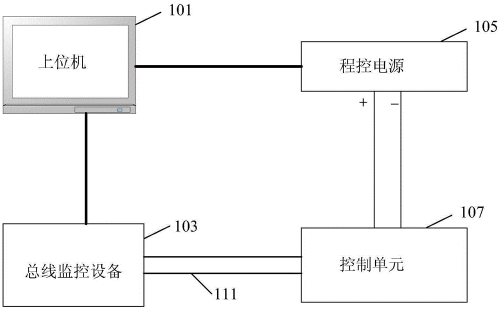
[0021] figure 1 It is a main frame diagram of the CAN bus test system provided by the first embodiment of the present invention. Please refer to figure 1 , The CAN bus test system includes: a host computer 101, a bus monitoring device 103, a program-controlled power supply 105, and a control unit 107.
[0022] Wherein, the upper computer 101 is connected with the program-controlled power supply 105 and the bus monitoring device 103, and is used to send the voltage control instruction simulating the voltage waveform output by the storage battery during the starting process of the automobile engine to the program-controlled power supply 105 according to the set voltage waveform.
[0023] Among them, specifically, the upper computer 101 can set the voltage waveform through the CAPL program of the CANoe software platform set in it, so as to simulate the change of the battery power supply voltage during the starting process of the car, so as to automatically control the programmab...
no. 2 example
[0047] Figure 4 It is a flowchart of the steps of the CAN bus testing method provided by the second embodiment of the present invention. Please refer to Figure 4 , the equipment required by the method includes a host computer, a bus monitoring device, a program-controlled power supply, and a control unit. The CAN bus testing method of this embodiment includes the following steps 401-409.
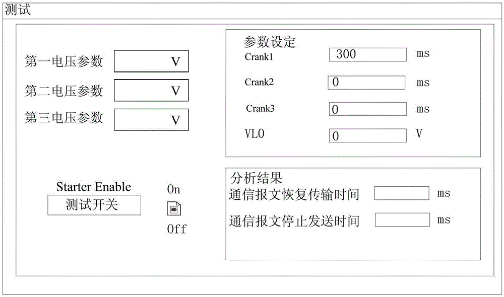
[0048] Step 401, according to the set voltage waveform, the upper computer sends a voltage control instruction simulating the voltage waveform output by the battery during the starting process of the automobile engine to the program-controlled power supply; wherein, preferably, the upper computer also adjusts multiple voltage parameters to set Determine the voltage waveform of different car models.
[0049] Step 403, the programmable power supply outputs the power supply voltage to the control unit according to the voltage control instruction sent by the host computer;
[0050] Step 405, ...
no. 3 example
[0059] Figure 5 It is a flow chart of the steps of the CAN bus testing method provided by the third embodiment of the present invention. Figure 5 is in Figure 4 improved on the basis of Figure 5 and Figure 4 The difference is that Figure 5 Each step of the Figure 4 Specific refinement steps for each step. Please refer to Figure 5 , the CAN bus testing method of the embodiment of the present invention may include the following steps 501-509.
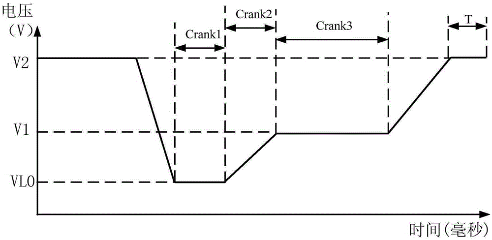
[0060] Step 501, the host computer also sends a voltage control command to the programmable power supply according to the first preset time period in the set voltage waveform and the first voltage parameter, and records the sending time of the communication message;
[0061] Step 503, the programmable power supply outputs the first power supply voltage to the control unit according to the voltage control instruction sent by the host computer and keeps outputting the first power supply voltage for a first preset time period;...
PUM
 Abstract
Description
Claims
Application Information