Solar module

A technology for solar modules and solar cells, applied in the field of solar modules, can solve the problems of increasing the size of the outlet holes on the backplane, damage and failure of the solar module, etc., and achieve the effects of reducing the amount of entry, improving the waterproofness, and being convenient to manufacture.

Active Publication Date: 2016-03-16
ARCHERS
View PDF6 Cites 6 Cited by
  • Summary
  • Abstract
  • Description
  • Claims
  • Application Information

AI Technical Summary

Problems solved by technology

However, for example, turning over the back panel at the outlet hole to increase the distance between the wire and the metal layer of the back panel will increase the size of the outlet hole on the back panel, making it easy for water vapor to enter the solar energy through the outlet hole. module, resulting in solar module damage and failure

Method used


Image

  • Solar module
  • Solar module
  • Solar module

Examples


Embodiment Construction

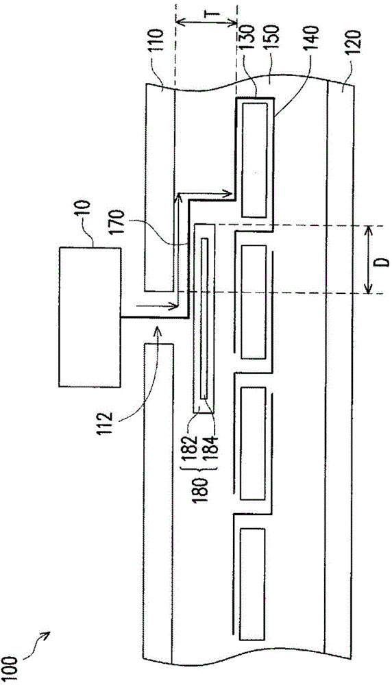
[0040] figure 1 is a partial cross-sectional schematic diagram of a solar module according to an embodiment of the present invention. see figure 1 , the solar module 100 of this embodiment includes a backplane 110, a light-transmitting substrate 120, a plurality of solar cells 130 disposed between the backplane 110 and the light-transmitting substrate 120, and a plurality of secondary wires 140 connecting these solar cells 130 , a sealing layer 150 arranged between the back plate 110 and the light-transmitting substrate 120 and covering the solar cell 130 and the secondary wires 140 , a plurality of main wires 170 connected to these secondary wires 140 , and the back surface buried in the sealing layer 150 A water-blocking insulating layer 180 is formed in the area between the panel 110 and the solar cell 130 .

[0041] The secondary wire 140 is connected to the solar cell 130 and collected to the main wire 170 . Since the sub-wire 140 is connected with the main wire 170, i...


PUM


Abstract

The invention discloses a solar module, and the module comprises a back plate, a light transmission substrate, a plurality of solar cells, a plurality of auxiliary wires, a sealing layer, a plurality of main wires, and a water-resisting insulating layer. The back plate is provided with a wire outgoing hole. The solar cell is disposed between the back plate and the light transmission substrate. The auxiliary wires are connected with the solar cells and are gathered to the main wires. The sealing layer is disposed between the back plate and the light transmission substrate, and covers the solar cells and the auxiliary wires. The main wires pass through the sealing layer and the wire outgoing holes to be connected to a junction box. The water-resisting insulating layer is embedded in a region, between the back plate and the solar cell, in the sealing layer, and is corresponding to the position of the wire outgoing hole, thereby enabling the projection of the water-resisting insulating layer towards the back plate to at least cover the wire outgoing hole.

Description

technical field [0001] The present invention relates to a solar module, and in particular to a solar module with better water resistance. Background technique [0002] With the rising awareness of environmental protection, the concept of energy saving and carbon reduction has gradually attracted people's attention. The development and utilization of renewable energy has become the focus of active development by countries all over the world. Among the renewable energy sources, since sunlight is available everywhere, and unlike other energy sources (such as petrochemical energy, nuclear energy), which generally pollute the earth, solar energy and various devices that can convert sunlight into electrical energy are currently promising stars industry. [0003] Generally speaking, the backplane of the solar module has a hole for the wires connected to the solar cells to pass through the backplane. U.S. Patent Nos. US8461450, US2010 / 0229937 and US2010 / 0236623 disclose that insul...

Claims


Application Information

Patent Timeline
Patent Type & Authority Applications(China)
IPC IPC(8): H01L31/048
CPCY02E10/50
Inventor 吴建树
Owner ARCHERS
Why Eureka
Try Eureka