Rotary electromagnet with symmetric magnetic paths

A rotating electromagnet, symmetrical technology, applied in the field of rotating electromagnet, can solve the problems of time-consuming and laborious, and achieve the effect of convenient processing and simple structure

Inactive Publication Date: 2016-03-16
ZHEJIANG COLLEGE OF ZHEJIANG UNIV OF TECHOLOGY
View PDF4 Cites 2 Cited by
  • Summary
  • Abstract
  • Description
  • Claims
  • Application Information

AI Technical Summary

Problems solved by technology

[0004] In order to overcome the problem that the existing magnetic circuit symmetric rotary electromagnet stator and rotor cannot be processed by traditional machining methods, special injection molds ...

Method used


Image

  • Rotary electromagnet with symmetric magnetic paths
  • Rotary electromagnet with symmetric magnetic paths
  • Rotary electromagnet with symmetric magnetic paths

Examples


Embodiment Construction

[0024] The present invention will be further described below in conjunction with the accompanying drawings.

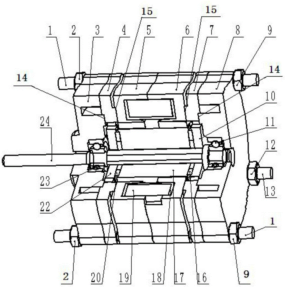
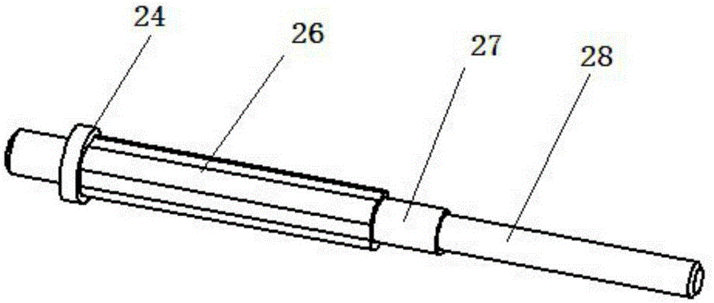
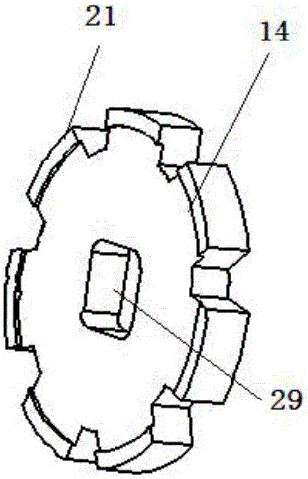
[0025] refer to Figure 1-7 As shown, a rotating electromagnet with a symmetrical magnetic circuit includes a front cover 3 and a rear end cover 8. A rotor component is installed on the front cover 3 and the rear end cover 8, and the front cover on both sides of the rotor component 3 and the rear end cover 8 are respectively equipped with a stator part; the rotor part includes a rotor shaft 24 mounted on the front end cover 3 and the rear end cover 8 through the first bearing 23 and the second bearing 11, which can rotate around the central axis, Both sides of the rotor shaft 24 are respectively equipped with a first permanent magnet 20, a second permanent magnet 16, a first rotor segment 22, a second rotor segment 17 and a third rotor segment 10; Yoke 4 , second yoke 5 , third yoke 6 , fourth yoke 7 , coil 19 , and coil holder 18 .

[0026] The second yoke 5 and the...


PUM


Abstract

The invention discloses a rotary electromagnet with symmetric magnetic paths. The rotary electromagnet comprises a front fragment cover and a rear end cover, wherein a rotor part is arranged on the front fragment cover and the rear end cover, stator parts are respectively arranged on the front fragment cover and the rear end cover at the two sides of the rotor part, the rotor part comprises a rotor shaft, the rotor shaft is arranged on the front fragment cover and the rear end cover via a first bearing and a second bearing and can rotate around a central axial line, a first permanent magnet, a second permanent magnet, a first rotor fragment, a second rotor fragment and a third rotor fragment are arranged at each of the two sides of the rotor shaft, and each stator part comprises a first yoke, a second yoke, a third yoke, a fourth yoke, a coil and a coil retaining rack. With the improved dual-magnetic steel electromagnetic design, the rotary electromagnet with the symmetric magnetic paths also can be fabricated by a mechanical processing mode, is simple in structure and is convenient to process.

Description

technical field [0001] The invention belongs to an electric-mechanical energy conversion device in the field of fluid transmission and control, in particular to a rotating electromagnet with a symmetrical magnetic circuit. Background technique [0002] In recent years, the 2D digital servo valve using the principle of servo screw mechanism has been widely used in metal material testing machines, earthquake simulation shaking tables and related aerospace fields because of its simple structure, fast response speed, high precision, and strong anti-pollution ability. have been widely used. Conventional electro-mechanical converters for 2D digital servo valves are generally rotary electromagnets with mixed excitation. Compared with the former, it has the following advantages: First, it adopts axial phase separation, and the control winding can use toroidal coils. The winding and off-line process is simple, and the coil paint is not easy to be damaged. structure; second, the axi...

Claims


Application Information

Patent Timeline
IPC IPC(8): H02K1/27H02K1/14
Inventor 周建华孟彬方珠芳
Owner ZHEJIANG COLLEGE OF ZHEJIANG UNIV OF TECHOLOGY
Why Eureka
Try Eureka