Liquid spray foam remover applied to rectifying tower

A rectifying tower and demister technology, applied in the field of liquid mist demister, can solve the problems of inability to remove, high cost, poor mist removal effect, etc. Effect

Active Publication Date: 2016-03-23
SHENZHEN SUNEVAP TECH
View PDF6 Cites 6 Cited by
  • Summary
  • Abstract
  • Description
  • Claims
  • Application Information

AI Technical Summary

Problems solved by technology

However, because the cyclone demister demisters through a centrifugal device, it requires a high inlet gas velocity, and at the same time the separation efficiency is not high, and it is not easy to separate the mist with a small particle size, so it cannot treat the removal of "liquid foam and mist". Foam” for precise removal
Since the wire mesh demister is demistered through the wire mesh, there are set requirements for the separation "particle size" and the air flow velocity. Therefore, the removal effect of the heavily entrained mist is poor
Moreover, the efficiency of the existing demisters is generally low from the perspective of mass transfer and heat transfer, and the existing demisters are sheet-shaped structures, and the distance between the sheets is relatively large. This is an unfavorable factor on its surface. Easy to accumulate dust and scale, difficult to clean
High cost, inconvenient installation and maintenance

Method used


Image

  • Liquid spray foam remover applied to rectifying tower
  • Liquid spray foam remover applied to rectifying tower
  • Liquid spray foam remover applied to rectifying tower

Examples


Embodiment Construction

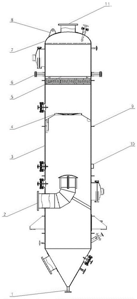
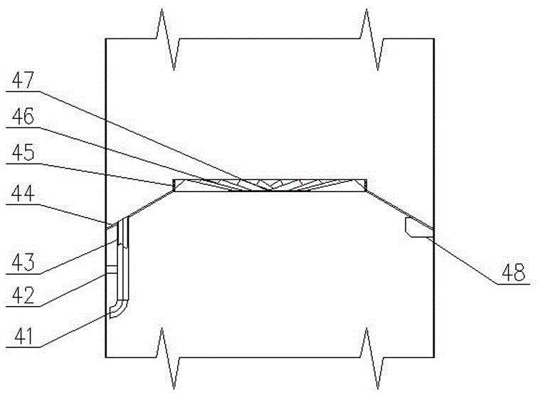
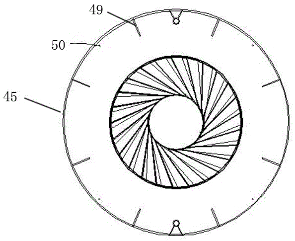
[0020] see Figure 1-4 As shown, the present invention relates to a liquid mist eliminator applied to a rectification tower, comprising a rectification tower shell 3, the top, middle and bottom of the rectification tower shell 3 are respectively provided with a gas outlet 11, a liquid The mist synthesis gas inlet 2 and the liquid outlet 1, the gas outlet 11 are provided with concave and convex surface loose tube flanges 7 and convex surface loose tube flanges 8, and the outer wall of the rectification tower shell 3 is provided with top to bottom respectively There are hanging lugs 6, circulating material inlet and outlet components 9, and sight glass flushing port components 10. The rectification tower shell 3 is provided with a guide ring 5 and a swirl defoaming component 4. The guide ring 5 is provided with Below the gas outlet 11 and above the cyclone demister assembly 4, the cyclone demister assembly 4 is located above the liquid mist synthesis gas inlet 2, and the cyclone...


PUM


Abstract

A liquid spray foam remover applied to a rectifying tower comprises a rectifying tower shell. A gas outlet, a liquid spray synthesis gas inlet and a liquid outlet are formed in the top, the middle and the bottom of the rectifying tower shell respectively. A loose tube flange is arranged at the gas outlet. A hanging lug, a circulation material inlet and outlet assembly and a sight glass flushing opening assembly are arranged on the outer wall of the rectifying tower shell from top to bottom. A guide ring and a rotation flow foam removal assembly are arranged in the rectifying tower shell. The guide ring is arranged below the gas outlet and on the rotation flow foam removal assembly. The rotation flow foam removal assembly is arranged above the liquid spray synthesis gas inlet. A cone shell is fixed to the inner wall of the rectifying tower shell. A cover cylinder is fixedly arranged on the cone shell. A liquid collection groove is formed in the top of the cover cylinder. An overflow pipe is arranged along the cone shell and communicated with the liquid collection groove. A circular plate with a hole in the center serves as a blind plate which is arranged at the bottom of the cover cylinder. Rotational flow blades are evenly arranged in the cover cylinder and arranged above the blind plate.

Description

technical field [0001] The invention relates to the field of liquid mist filtration and removal of mist in gaseous fluid during medicinal liquid extraction, in particular to a liquid mist eliminator applied to a rectification tower. Background technique [0002] In the production of chemical industry, petrochemical industry and oil refining, the tower equipment is one of the important equipment, which mainly plays the role of gas (or steam) or liquid two-phase close contact to achieve interphase mass transfer and heat transfer. In chemical, petrochemical and other application fields, the performance of tower equipment has a significant impact on the production capacity, consumption quota, three waste treatment and environmental protection of the entire equipment. In the existing plate tower and packed tower equipment, in the operation of gas-liquid mass transfer and heat transfer units such as rectification, absorption, desorption, increase (decrease) humidity, etc., it is t...

Claims


Application Information

Patent Timeline
Patent Type & Authority Applications(China)
IPC IPC(8): B01D45/08B01D45/02B01D3/14
CPCB01D3/14B01D45/02B01D45/08
Inventor 郭亮周齐张小江鲍燕娟牛柯
Owner SHENZHEN SUNEVAP TECH
Why Eureka
Try Eureka