Box turnover and sand strip system for casting wear-resisting parts
A wear-resistant part and box-turning technology, which is applied in casting and molding equipment, molding machines, manufacturing tools, etc., can solve the problems of unachievable requirements for sanding operations, high manufacturing costs, and complex structure of vibration shakeout machines, reducing the need for The effect of manual workload, energy saving and accurate positioning
- Summary
- Abstract
- Description
- Claims
- Application Information
AI Technical Summary
Problems solved by technology
Method used
Image
Examples
Embodiment 1
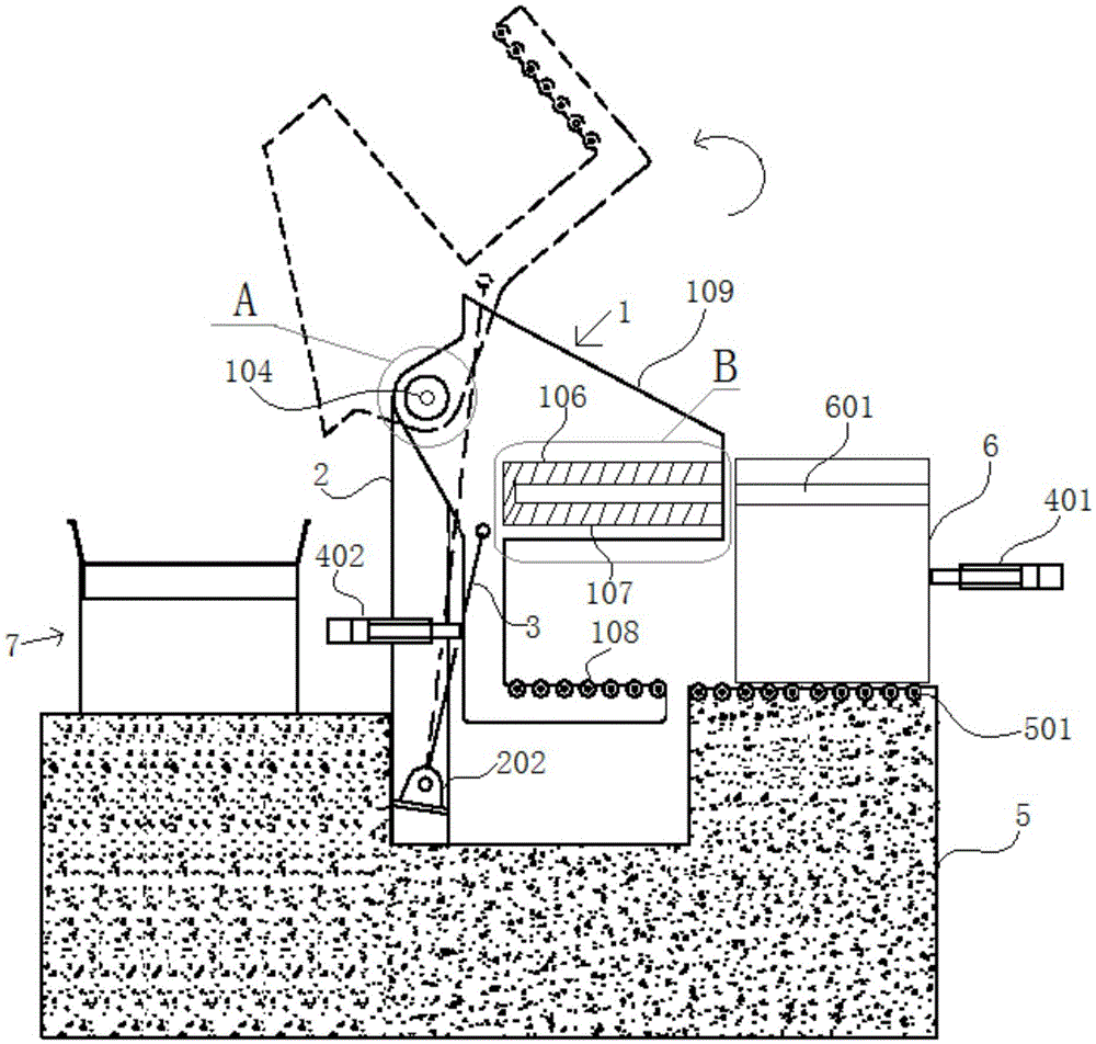
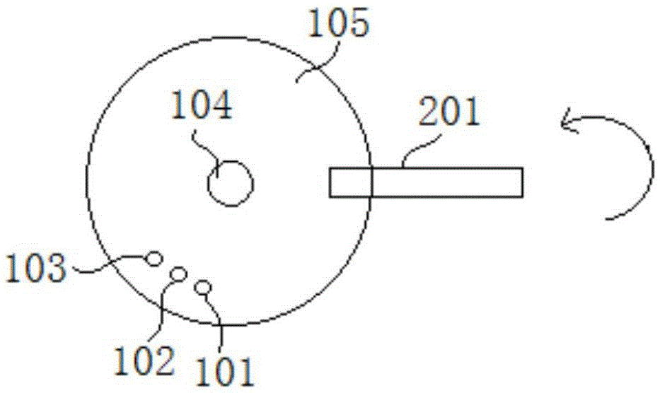
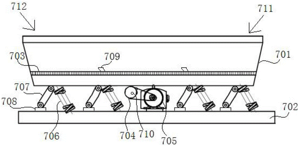
[0047] combine Figure 1~3 , the present embodiment of the wear-resistant casting casting sand removal system includes a sand box turning device and a sand removal device 7 . The sand box overturning device includes a rotating arm 1, a frame 2, a telescopic arm 3, a base 5 and a sand box 6, the frame 2 is fixed on the base 5, the rotating arm 1 is hinged on the frame 2, the telescopic arm 3 and the rotating arm 1 Connected, the telescopic arm 3 is used to push the rotating arm 1 to rotate with the hinge point of the rotating arm 1 and the frame 2 as the center of a circle, and the rotating arm 1 is used to install the sand box 6 . In this embodiment, the sand box turning device is specifically: the rotating arm 1 includes an upper sand box cover 109 and a lower rotating arm main body, the rotating arm main body includes a lower bottom plate and a side plate, and the lower end of the side plate is vertically fixed on the lower bottom plate, The upper end of side plate is fixed...
Embodiment 2
[0055] The structure of the box-turning and desanding system for wear-resistant parts casting in this embodiment is basically the same as that of Example 1, the difference is that: in the sand box turning device, both the push-in arm 401 and the push-out arm 402 are hydraulic cylinders;
[0056] In the desanding device 7, the angle between the baffle plate 709 and the vertical line is 45°; the through hole diameter on the sieve plate 703 between the material input end 711 and the first baffle plate is 10mm, and the first baffle plate and the second The diameter of the through hole on the sieve plate 703 between the two baffle plates is 15 mm, and the diameter of the through hole on the sieve plate 703 between the second baffle plate and the material output end 712 is 20 mm.
Embodiment 3
[0058] The structure of the flipping and desanding system for wear-resistant parts casting in this embodiment is basically the same as that of Embodiment 1, the difference is that in order to ensure that the recovered molding sand is not mixed with small particles of metal impurities, at the material input end 711 There is a magnetic separator above, and the magnetic separator is used to magnetically separate the molding sand entering the conveying tank 701 to remove small particles of metal impurities in the molding sand; in order to improve the working environment on site and avoid air pollution, there is also a There is a dust collection cover, which can absorb the dusty air above the conveying trough 701. At the same time, the castings that have just been cast not only have high heat, but also emit some toxic and harmful gases. Toxic and harmful gas pumping effect.
PUM
 Abstract
Description
Claims
Application Information
 - R&D
- Intellectual Property
- Life Sciences
- Materials
- Tech Scout
- Unparalleled Data Quality
- Higher Quality Content
- 60% Fewer Hallucinations
Browse by: Latest US Patents, China's latest patents, Technical Efficacy Thesaurus, Application Domain, Technology Topic, Popular Technical Reports.
© 2025 PatSnap. All rights reserved.Legal|Privacy policy|Modern Slavery Act Transparency Statement|Sitemap|About US| Contact US: help@patsnap.com


