
Isolation double-stage chain type current transformer applied to energy storage of high-capacity battery

A chain converter, battery energy storage technology, applied in flexible AC transmission systems, single-grid parallel feeding arrangements, etc., can solve problems affecting battery maintenance, reducing the safety and reliability of battery energy storage systems, and adversely affecting battery module production. and other problems, to achieve the effect of easy modular production, reduction of secondary pulsation power, and reduction of requirements

Active Publication Date: 2013-09-04
SHANGHAI JIAO TONG UNIV
View PDF3 Cites 16 Cited by
  • Summary
  • Abstract
  • Description
  • Claims
  • Application Information

AI Technical Summary

Problems solved by technology

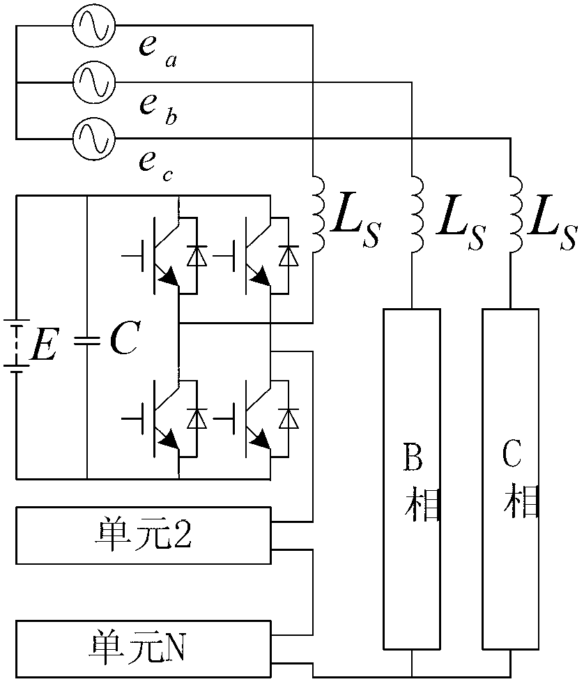
As a power conversion system for energy storage, chain-link converters such as figure 1 , because there is no isolation transformer, the different battery modules in each phase have a large common-mode voltage with the grid side, and the higher voltage is not conducive to the production of battery modules, and greatly affects the maintenance of the battery by the staff, etc. Reduce the safety and reliability of the battery energy storage system

Method used


Image

  • Isolation double-stage chain type current transformer applied to energy storage of high-capacity battery
  • Isolation double-stage chain type current transformer applied to energy storage of high-capacity battery
  • Isolation double-stage chain type current transformer applied to energy storage of high-capacity battery

Examples


Embodiment Construction

[0019] The present invention will be described in detail below in conjunction with specific embodiments. The following examples will help those skilled in the art to further understand the present invention, but do not limit the present invention in any form. It should be noted that those skilled in the art can make several modifications and improvements without departing from the concept of the present invention. These all belong to the protection scope of the present invention.

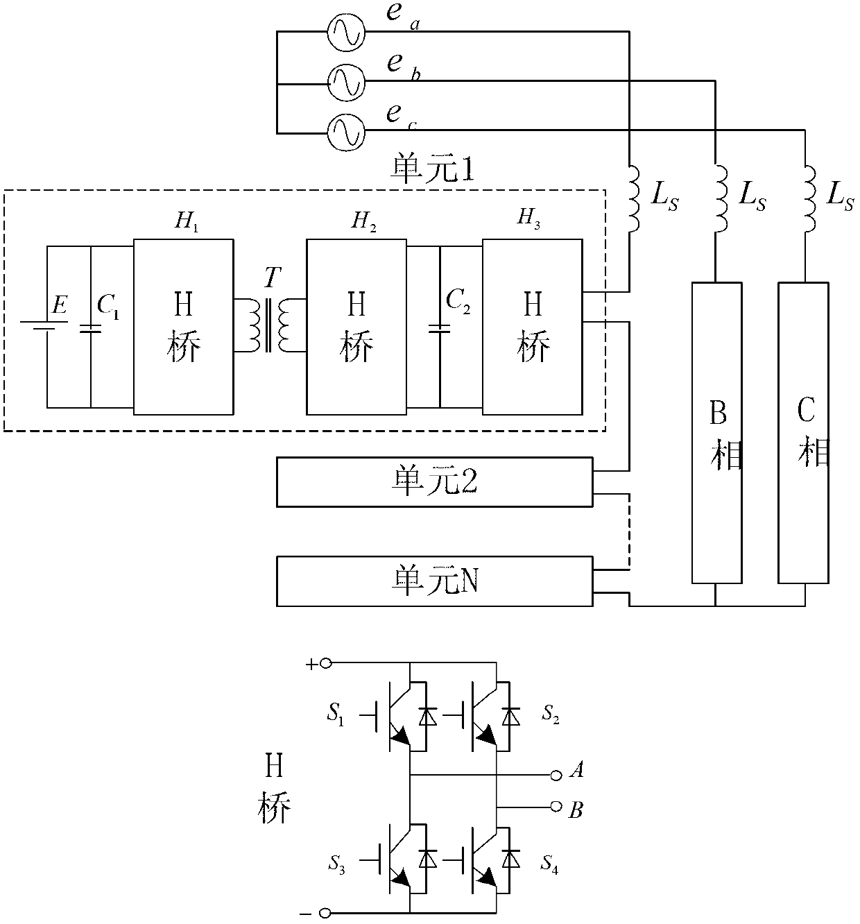
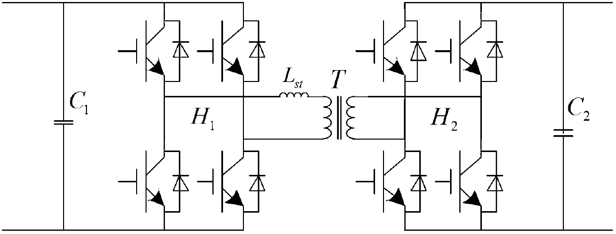
[0020] refer to figure 2 , this embodiment provides an isolated two-stage chain-link converter topology applied to large-capacity battery energy storage, including battery modules E, units, and grid-connected reactors L in the battery energy storage system s . Each phase of this topology is composed of N units in series, and the three phases are connected in a star shape, through the reactor L s Connect directly to the high voltage grid. The unit is composed of battery module E, battery side c...


PUM


Abstract

The invention provides an isolation double-stage chain type current transformer applied to energy storage of a high-capacity battery. A bidirectional isolation full-bridge current transformer with a high-frequency isolation current transformer is additionally arranged between each H bridge module of a conventional chain type current transformer and the battery, so that a battery side is insulated from a high-voltage power grid. The bidirectional isolation full-bridge current transformer is controlled to keep voltage of a middle direct-current side; meanwhile, secondary pulse power on the battery side of the chain type current transformer can be buffered; a chain type energy-storing current transformer can be used as an interface of battery energy storage and the power grid, so that high-voltage direct-current grid connection can be realized, the power dispatching of the power grid is accomplished, and the volumes of harmonic and filter elements of an energy storage system, which are accessed into the power grid, can also be reduced. According to the isolation double-stage chain type current transformer disclosed by the invention, the requirements on an insulation grade of a battery module can be reduced, the secondary pulse power on the battery side is reduced, and the safety and the reliability of the battery are guaranteed; and meanwhile, different types of batteries with different voltage grades can be accessed so that the isolation double-stage chain type current transformer can be easily produced in a large scale, and is suitable for a large-capacity, high-voltage and grid-connected battery energy storing system.

Description

technical field [0001] The invention relates to the technical field of electrical automation equipment, in particular to an isolated two-stage chained converter topology applied to large-capacity battery energy storage. Background technique [0002] Due to its fast response, high energy density, good environmental conditions, and mature technology, battery energy storage systems have been widely used in various aspects of the power system, especially in load balancing, user-side power quality, reactive power compensation, and accommodation. Highlighting strengths in important issues such as renewable energy. [0003] The chain topology is widely used in high-voltage motor drive inverters, high-voltage reactive power compensation and other fields; this topology can also be used as an energy storage converter and directly connected to the high-voltage power grid. As a power conversion system for energy storage, chain-link converters such as figure 1 , because there is no iso...

Claims


Application Information

Patent Timeline
Patent Type & Authority Applications(China)
IPC IPC(8): H02J3/38
CPCY02E40/10
Inventor 蔡旭陈强李睿
Owner SHANGHAI JIAO TONG UNIV
Learn More