Steel pipe cutting machine

A technology for pipe cutting machines and steel pipes, which is applied in the direction of pipe shearing devices, shearing devices, and attachments of shearing machines, etc., and can solve problems such as long labor load and operation time, inaccurate focusing effect, and complex structure of pipe cutting machines. , to achieve good job quality, convenient operation, saving working time and labor

Inactive Publication Date: 2016-03-23
WUXI CHENYUAN CONSTR EQUIP
View PDF10 Cites 7 Cited by
  • Summary
  • Abstract
  • Description
  • Claims
  • Application Information

AI Technical Summary

Problems solved by technology

[0002] Pipe cutting machine is a commonly used equipment in pipe processing, but the current pipe cutting machine has complex structure, large volume, large space occupation, inconvenient operation, and poor automation performance. To complete the process, not only the amount of labor consumed and the time of operation are longer, but also the work efficiency is reduced. In addition, the existing equipment has poor precision, weak motor power, inaccurate focusing effect, and slightly inaccurate during processing. Be careful, it may happen that the cut pipe is slightly longer or shorter, which does not meet the needs of customers, and causes economic losses to the processing factory.

Method used


Image

  • Steel pipe cutting machine
  • Steel pipe cutting machine

Examples


Embodiment Construction

[0017] The following will clearly and completely describe the technical solutions in the embodiments of the present invention with reference to the accompanying drawings in the embodiments of the present invention. Obviously, the described embodiments are only some, not all, embodiments of the present invention. Based on the embodiments of the present invention, all other embodiments obtained by persons of ordinary skill in the art without making creative efforts belong to the protection scope of the present invention.

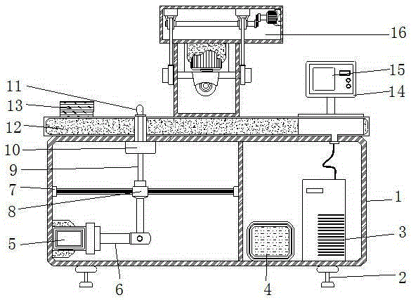
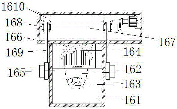
[0018] see Figure 1-2 , the present invention provides a technical solution: a steel pipe cutting machine, including a cabinet 1, a work surface 12, a control panel 14 and a pipe cutter 16, and the right side of the inner cavity of the cabinet 1 is respectively equipped with a control host 3 and a power supply box 4 , and the left side of the cavity is also equipped with an air pump 5, the right side of the air pump 5 is connected with a telescopic arm 6, the...


PUM


Abstract

The invention discloses a steel pipe cutting machine which comprises a machine box, a work table board, a control panel and a pipe cutter. An automatic calibrator is arranged on the outer wall of a movable main rod. A propeller, the control panel and the pipe cutter are arranged at the top of the work table board. A knife control box is arranged at the bottom of the pipe cutter. Lifters are arranged on the left side and the right side of the outer wall of the knife control box. A maneuvering box is arranged at the top of the knife control box. The steel pipe cutting machine is simple in structure, small in size, reasonable in occupied space, convenient to operate, high in automation performance and high in flexibility, maneuverability, precision and practicality; and the propeller is arranged on the work table board of the steel pipe cutting machine, an automatic feeding device is adopted in the steel pipe cutting machine, excessive auxiliary of workers is not needed, and therefore work time and the labor workload are saved, and work efficiency is improved.

Description

technical field [0001] The invention relates to the technical field of metal pipe processing, in particular to a steel pipe cutting machine. Background technique [0002] Pipe cutting machine is a commonly used equipment in pipe processing, but the current pipe cutting machine has complex structure, large volume, large space occupation, inconvenient operation, and poor automation performance. Complete the process, thus not only the amount of labor consumed and the operating time are longer, but also the operating efficiency is reduced. In addition, the existing equipment has poor precision, weak motor power, and the focusing effect is not accurate enough. During processing, there is a slight error Be careful, it may happen that the cut pipe is slightly longer or shorter, which does not meet the needs of customers, and causes economic losses to the processing factory. Contents of the invention [0003] The purpose of the present invention is to provide a steel pipe cutting...

Claims


Application Information

Patent Timeline
Patent Type & Authority Applications(China)
IPC IPC(8): B23D19/00B23D21/00B23D33/02B23D33/00
CPCB23D19/00B23D21/00B23D33/00B23D33/02
Inventor 潘燕清
Owner WUXI CHENYUAN CONSTR EQUIP
Why Eureka
Try Eureka