A Method for Improving the Performance of Thin Plate Friction Stir Welding Joints

A friction stir and welding joint technology, which is applied in welding equipment, welding/welding/cutting items, non-electric welding equipment, etc., can solve the problems of low bearing capacity of joints, difficult tooling, etc., and achieve improved inclusiveness, increased bearing area, and increased The effect of overall weight

Inactive Publication Date: 2017-11-17
HARBIN INST OF TECH
View PDF3 Cites 0 Cited by
  • Summary
  • Abstract
  • Description
  • Claims
  • Application Information

AI Technical Summary

Problems solved by technology

[0004] The present invention provides a method for improving the performance of thin plate friction stir welding joints, so as to solve the problems of existing thin plate friction stir welding tooling difficulties and low joint bearing capacity.

Method used


Image

  • A Method for Improving the Performance of Thin Plate Friction Stir Welding Joints
  • A Method for Improving the Performance of Thin Plate Friction Stir Welding Joints
  • A Method for Improving the Performance of Thin Plate Friction Stir Welding Joints

Examples


specific Embodiment approach 1

[0034] Specific implementation mode one: combine Figure 1 to Figure 4 and Figure 6 Describe this embodiment, a method for improving the performance of a thin plate friction stir welded joint in this embodiment, it includes the following steps:

[0035] Step 1. Preparation of butt welding plate:

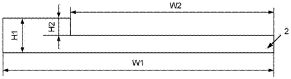
[0036]The butt welding plate 2 is processed by machining, and the length L1 is 200-400mm, the width W1 is 80-120mm, and the thickness H1 is 2-6mm; the butt welding plate 2 is milled, and the position of the milling is In order to carry out milling on the upper end surface of the butt welding plate 2 along its width direction based on one of the sides in the length direction, after milling off part of the plane, a boss with the same length as the butt welding plate 2 is left, and the milling width W2 is 60-100mm, milling depth H2 is 1-3mm;

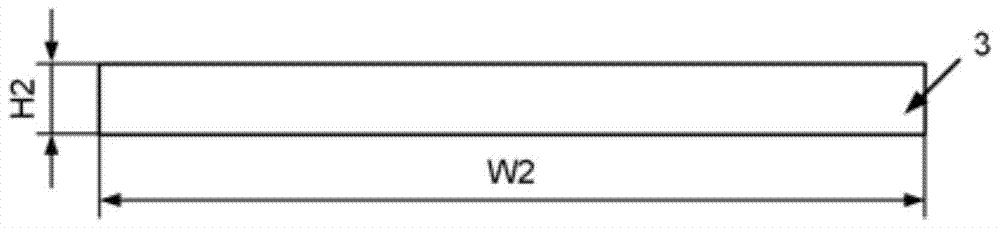
[0037] Step 2, preparation of auxiliary board:

[0038] The auxiliary plate 3 is processed by machining, the length of the auxiliary plate 3...

specific Embodiment approach 2

[0045] Specific implementation mode two: combination Figure 1 to Figure 4 and Figure 6 To illustrate this embodiment, in step 1 of this embodiment, the length of the butt welding plate 2 is 300 mm, the width is 100 mm, the thickness is 4 mm, the milling width is 80 mm, and the milling depth is 2 mm. In this way, the thickness of the butt joint surface is 4mm, which can greatly reduce the difficulty of the plate butt joint tooling; the bearing capacity of the joint = joint strength × joint area, and the strength of the softening zone is about 60%-70% of the base metal, so the joint area should be the base metal Only 1.7-1.4 times of the base metal can guarantee the same bearing capacity as the base metal. Here, the thickness of the joint area is twice that of the base metal, and the load-bearing capacity of the joint area is more than 1.2 times that of the base metal. Even if there is weld thinning and small size The lack of welding will not significantly affect the load-bea...

specific Embodiment approach 3

[0046] Specific implementation mode three: combination Figure 1 to Figure 4 and Figure 6 To describe this embodiment, in step 2 of this embodiment, the width of the auxiliary plate 3 is 30 mm, and the thickness is 2 mm. Such setting ensures that the auxiliary plate 3 can provide good support for the butt welding plate 2 . Other connection methods are the same as those in Embodiment 1 or Embodiment 2.


PUM

PropertyMeasurementUnit
thicknessaaaaaaaaaa
lengthaaaaaaaaaa
widthaaaaaaaaaa

Abstract

The invention discloses a method for improving the performance of a sheet friction-stir welding head, relates to a friction-stir welding method, and aims to solve the problems of difficult tooling, low joint bearing capability and the like in the conventional sheet friction-stir welding process. The method provided by the invention comprises the following steps: step 1, preparing butt welding plates; step 2, preparing auxiliary plates; step 3, determining the size of a stirring head; step 4, performing assembly and fixing before welding, wherein the milling surface of the first butt welding plate faces down and the milling surface of the second butt welding plate faces up, or the milling surfaces of both the first and second butt welding plates face down, the first and second butt welding plates are butted with each other, and the first and second auxiliary plates are respectively placed on the milling surfaces of the first and second butt welding plates; step 5, performing welding. The method is applied to sheet friction-stir welding.

Description

technical field [0001] The invention relates to a method for friction stir welding, in particular to a method for improving the performance of a thin plate friction stir welding joint, which belongs to the field of welding technology. Background technique [0002] Friction stir welding is a solid-phase joining technology invented by the British Welding Institute in 1991. Compared with the traditional fusion welding method, it has the advantages of low heat input, small welding deformation, low energy consumption, and green and pollution-free. Aluminum alloys, magnesium alloys and other low-melting point light metal plates have obvious advantages when welding, and the advantages are more obvious when the thickness of the welded plates is 2mm or more. [0003] However, there are still several main technical problems in the friction stir welding of thin plates below 2 mm: (1) Due to the difficulty in guaranteeing parameters such as dimensional accuracy and parallelism of thin p...

Claims


Application Information

Patent Timeline
Patent Type & Authority Patents(China)
IPC IPC(8): B23K20/12B23K20/24B23K101/18
CPCB23K20/122B23K20/1255B23K20/24B23K2101/18
Inventor 刘会杰刘向前胡琰莹李继超王欢林喆曾凡勇
Owner HARBIN INST OF TECH
Why Eureka
Try Eureka