
Conveying device applied to glass production line

A glass production line and transportation device technology, applied in the direction of transportation and packaging, conveyor objects, furnaces, etc., can solve the problems of low automation, complex structure, high production cost, etc., achieve high automation, simple machine structure, and solve transportation problems Effect

Inactive Publication Date: 2016-03-23
SHENGZHOU HUANDING GLASS TECH CO LTD
View PDF0 Cites 14 Cited by
  • Summary
  • Abstract
  • Description
  • Claims
  • Application Information

AI Technical Summary

Problems solved by technology

[0002] During the production process, glass needs to go through steps such as glass plate cleaning and drying before entering the chemical tempering furnace and subsequent processing technology. Therefore, a glass transportation device is required to transfer the glass during the production process. The existing transportation device design for transit transportation of glass There are some defects, such as: (1) the structure is complex and the production cost is high; (2) the transfer transport device cannot be moved independently, and it needs to be placed on a mobile trailer to move, which is extremely inconvenient to move; (3) the transfer transport device is in the The glass cannot be fixed well during transportation, causing the glass to slip and break.
In addition, the use of this method not only has a low degree of automation, resulting in low work efficiency and high labor intensity, but also the operator is prone to safety accidents during work, and there are large safety hazards

Method used


Image

  • Conveying device applied to glass production line
  • Conveying device applied to glass production line
  • Conveying device applied to glass production line

Examples


Embodiment Construction

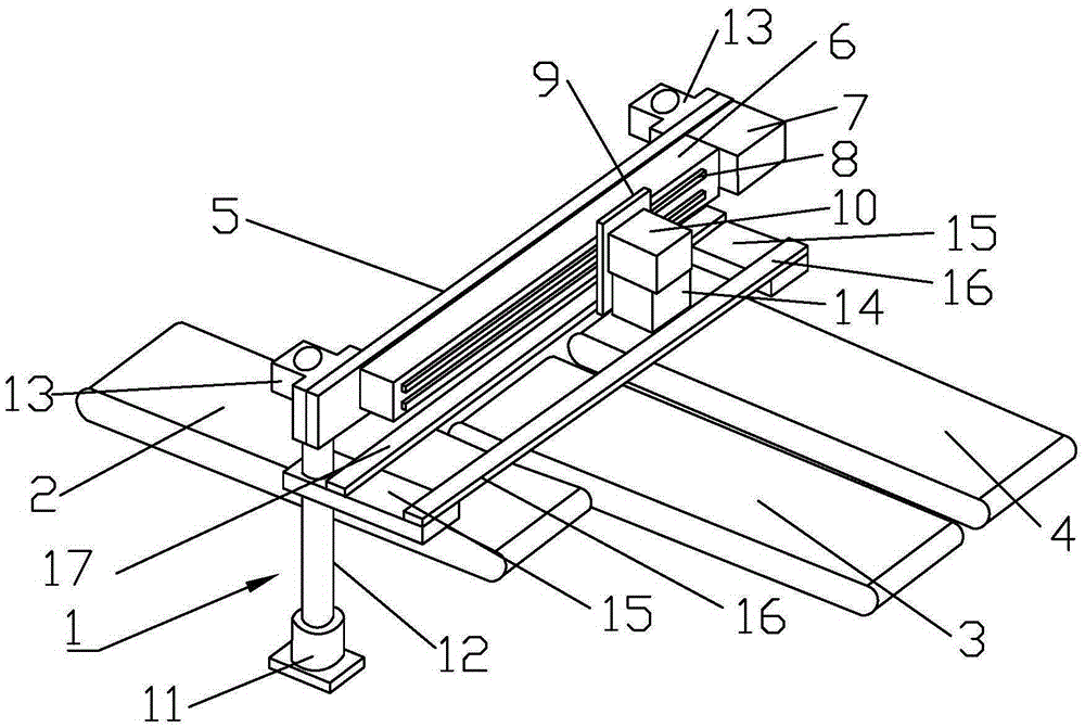
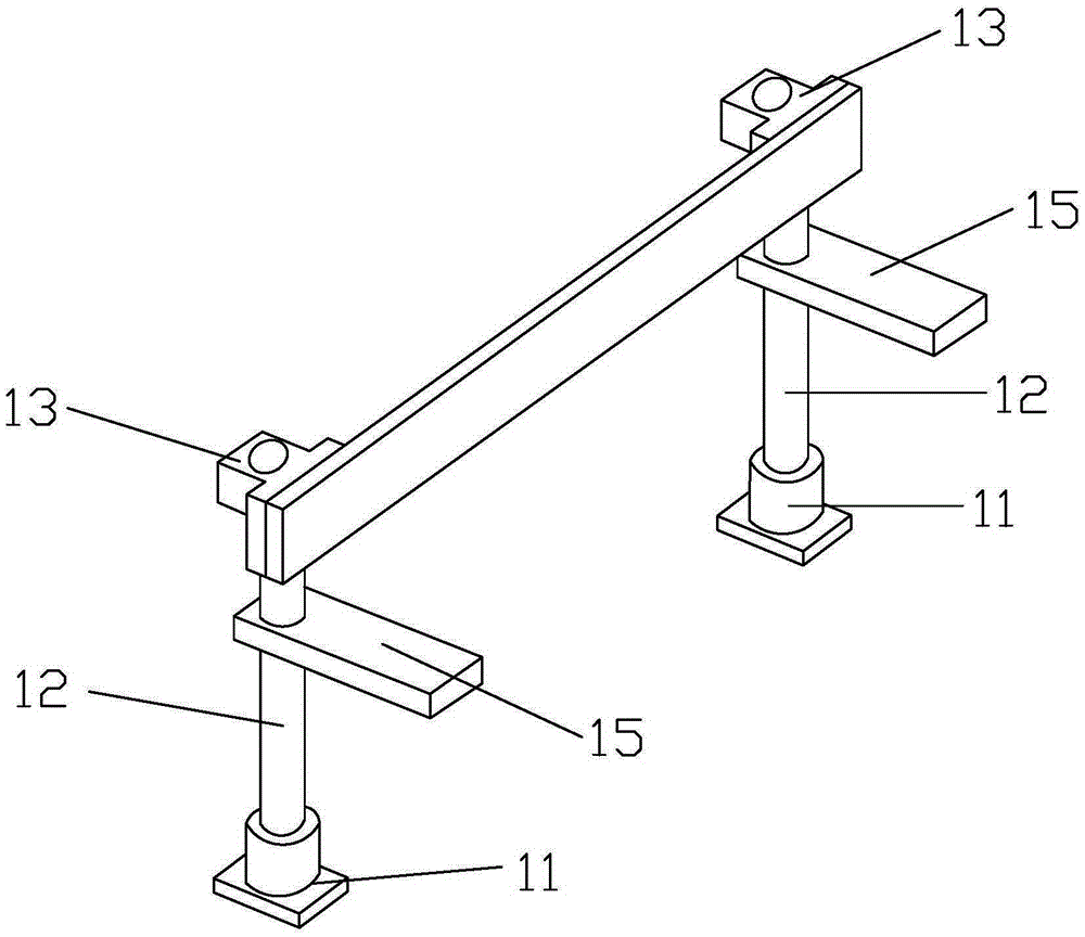
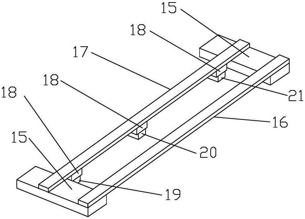
[0036] Such as Figure 1 to Figure 9 As shown, a transportation device applied to a glass production line includes a machine base 1 and a conveyor belt. A conveyor belt is provided under the machine base 1. The conveyor belt includes a feeding conveyor belt 2 and a production conveyor belt. The production conveyor belt includes a first Production conveyor belt 3 and second production conveyor belt 4 . The base 1 includes a connecting column 12, a supporting foot 11 and a connecting base 13, the upper end of the connecting column 12 is connected to the connecting base 13, the connecting base 13 is connected to the horizontal mounting plate 5, and the lower end of the connecting column 12 is connected to the supporting foot 11.

[0037] The machine base 1 is provided with a conveying device, and the conveying device includes a horizontal moving mechanism, a vertical lifting mechanism and a clamping mechanism. The base 1 is provided with a horizontal mounting plate 5, and the ho...


PUM


Abstract

The invention discloses a conveying device applied to a glass production line. The conveying device comprises a machine base and conveying belts. The conveying belts are arranged below the machine base. The conveying belts comprise the feeding conveying belt and the production conveying belts. The production conveying belts comprise the first production conveying belt and the second production conveying belt. A carrying device is arranged on the machine base and comprises a horizontal moving mechanism, a vertical lifting mechanism and a clamping mechanism. A horizontal installation plate is arranged on the machine base and provided with a horizontal moving mechanism. The horizontal moving mechanism comprises a horizontal fixing frame and a horizontal moving motor. The horizontal fixing frame is provided with a horizontal moving guide rail which is connected with a vertical lifting mechanism. The vertical lifting mechanism comprises a lifting air cylinder installation seat and a vertical lifting air cylinder. The lifting air cylinder installation seat is provided with the vertical lifting air cylinder. The vertical lifting air cylinder is connected with a clamping mechanism. The conveying device is simple in structure, scientific, convenient to use, high in pertinence, high in automation degree, high in work efficiency and capable of well solving the transportation problem of the glass production line.

Description

technical field [0001] The invention relates to a transportation device applied to a glass production line. Background technique [0002] During the production process, glass needs to go through steps such as glass plate cleaning and drying before entering the chemical tempering furnace and subsequent processing technology. Therefore, a glass transportation device is required to transfer the glass during the production process. The existing transportation device design for transit transportation of glass There are some defects, such as: (1) the structure is complex and the production cost is high; (2) the transfer transport device cannot be moved independently, and it needs to be placed on a mobile trailer to move, which is extremely inconvenient to move; (3) the transfer transport device is in the The glass cannot be fixed well during transportation, causing the glass to slip and break. In addition, the use of this method not only has a low degree of automation, resulting ...

Claims


Application Information

Patent Timeline
Patent Type & Authority Applications(China)
IPC IPC(8): B65G47/91B65G47/52B65G49/06
Inventor 应伟苹
Owner SHENGZHOU HUANDING GLASS TECH CO LTD
Learn More