
Polyethylene film winding and cutting mechanism

A polyethylene film and film cutting technology, which is applied in the direction of winding strips, thin material processing, and sending objects, can solve the problems affecting the normal progress of winding, achieve adjustability, increase friction, and facilitate operation Effect

Inactive Publication Date: 2016-03-23
ANQING XINSHUN PLASTIC CO LTD
View PDF8 Cites 2 Cited by
  • Summary
  • Abstract
  • Description
  • Claims
  • Application Information

AI Technical Summary

Problems solved by technology

[0010] Since the outer diameter of the winding device is much larger than that of the feeding roller, the winding movement of the winding device will drive the feeding roller to rotate rapidly, which will easily cause the film to wind loosely on the winding device, affecting the normal progress of winding

Method used


Image

  • Polyethylene film winding and cutting mechanism
  • Polyethylene film winding and cutting mechanism
  • Polyethylene film winding and cutting mechanism

Examples


Embodiment 1

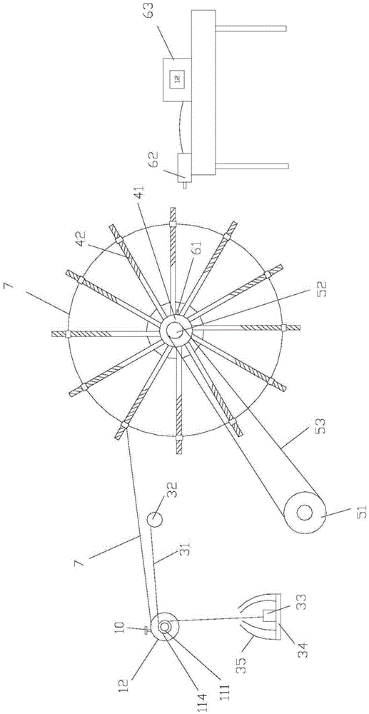
[0044] Such as Figure 1-2 As shown, the present embodiment includes a feeding device, a deceleration mechanism, a fixed-length winding device, and a driving device. The feeding device is arranged in front of the fixed-length winding device for feeding the film 7 to the fixed-length winding device, and the output of the driving device is connected to the fixed-length winding device.

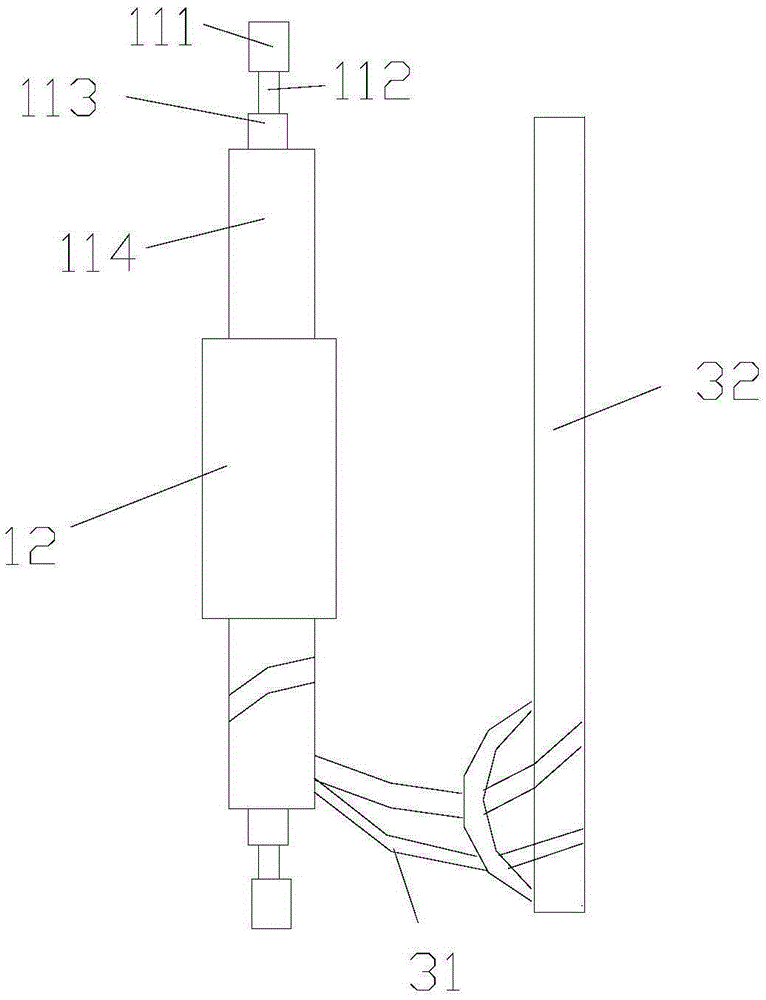
[0045] The feeding device includes a long shaft and a feeding cylinder 12. The long shaft includes a first shaft body 111, a second shaft body 112, a third shaft body 113, and a fourth shaft body 114 from the end to the middle area. The first shaft body 111 is the same as the outer diameter of the third shaft body 113 and is larger than the outer diameter of the second shaft body 112 and smaller than the outer diameter of the fourth shaft body 114; the feeding cylinder 12 is sleeved on the fourth shaft body 114, and the feeding cylinder 12 is provided with bolt 10 mounting holes.

[0046] Such as...

Embodiment 2

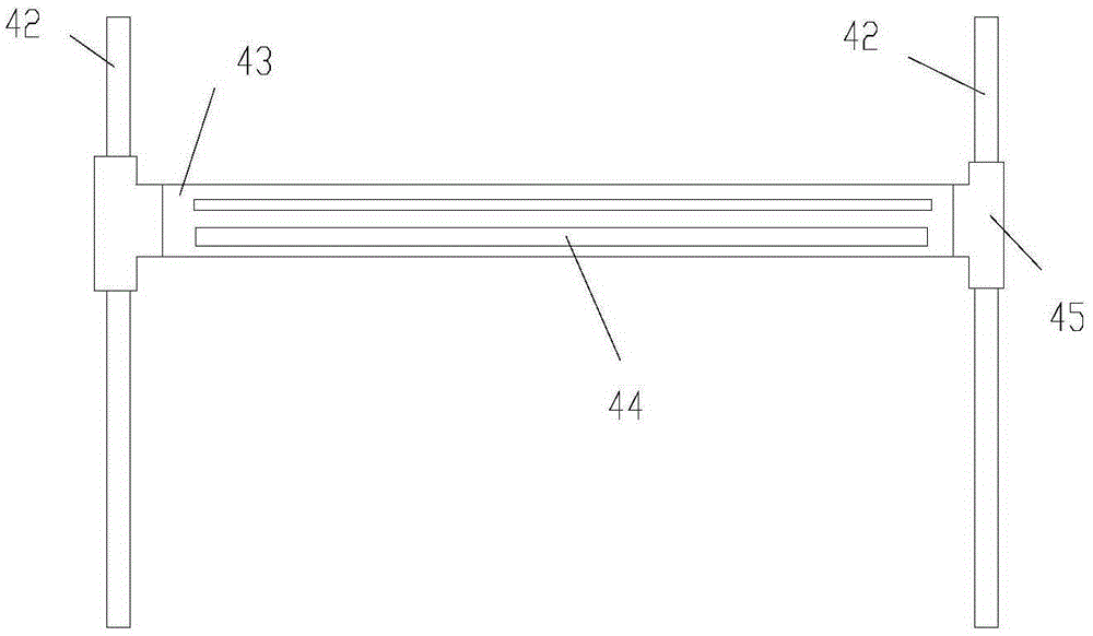
[0066] Such as Figure 8 As shown, the difference between this embodiment and Embodiment 1 is that the support rod 42 is provided with external threads, and the two ends of the cross bar 43 are sleeved on the corresponding support rods 42 respectively. Both upper and lower sides are provided with first nuts 47 , and the first nuts 47 are screwed on the corresponding support rods 42 .

[0067] The position of the cross bar 43 is adjusted by turning the first nut 47 .

Embodiment 3

[0069] Such as Figure 9 As shown, the difference between this embodiment and Embodiment 1 is that the lower end of the support rod 42 is provided with a positioning block 410, the positioning block 410 is provided with a spring sleeve 49, the upper end of the support rod 42 is spun with a second nut 48, and the cross bar The two ends of 43 are sleeved on the corresponding support rod 42 and located between the corresponding spring sleeve 49 and the second nut 48 .

[0070] By turning the second nut 48 and compressing the spring sleeve 49, the position of the cross bar 43 is adjusted.


PUM


Abstract

The invention discloses a polyethylene film winding and cutting mechanism which comprises a feeding device, a fixed-length winding device and a driving device, wherein the feeding device is arranged in front of the fixed-length winding device, and is used for feeding a film into the fixed-length winding device; the driving device is in output connection with the fixed-length winding device; a film cutting structure is arranged on the fixed-length winding device, and comprises a retarding mechanism; the retarding mechanism comprises an annular elastic band, a fixed rod and a weight; the fixed rod is parallel to the feeding device; one end of the annular elastic band is knotted on the fixed rod; the other end of the annular elastic band bypasses the feeding device; and the weight is suspended at the other end of the annular elastic band. The polyethylene film winding and cutting mechanism has the advantages that the structure is simple, the film length adjusting flexibility is high, the deviation of the feeding device is prevented, the abrasion of the feeding device is alleviated, and the film winding efficiency is improved.

Description

technical field [0001] The invention relates to the field of film technology, in particular to a polyethylene film winding and cutting mechanism. Background technique [0002] PE film, that is, polyethylene film, refers to a film produced from PE film. PE film has moisture resistance and low moisture permeability. Polyethylene film (PE) can produce products with different properties such as low-density, medium-density, high-density polyethylene and cross-linked polyethylene according to different manufacturing methods and control methods. [0003] PE film includes low-density polyethylene, medium-density polyethylene, and high-density polyethylene. [0004] Among them, the density of low-density polyethylene is about 0.92g / cm3. Low-density polyethylene film has good transparency and heat sealability, and can be waterproof and moisture-proof; it has low tensile strength, high tensile elongation, and is easy to wrinkle. For films below 0.03mm, the tension control should be ...

Claims


Application Information

Patent Timeline
Patent Type & Authority Applications(China)
IPC IPC(8): B65H23/188B65H20/02B65H18/10B65H35/06
CPCB65H23/1888B65H18/103B65H20/02B65H35/06B65H2701/10
Inventor 汪俊
Owner ANQING XINSHUN PLASTIC CO LTD
Learn More