Light electric trolley for crane

A technology of electric trolleys and cranes, which is applied in the direction of load-bearing blocks, spring mechanisms, load suspension components, etc., which can solve the problems of increased self-weight of the trolley frame, troublesome installation and adjustment, and loose overall structure, etc., and achieve the improvement of carrying capacity , easy maintenance and compact structure

Inactive Publication Date: 2016-03-23
HENAN SINOKO CRANES
View PDF7 Cites 0 Cited by
  • Summary
  • Abstract
  • Description
  • Claims
  • Application Information

AI Technical Summary

Problems solved by technology

[0002] In the crane, the electric trolley is mainly used to realize the lifting and moving of the goods. Among them, the lifting mechanism is the most important and basic mechanism in the electric trolley. Its structure directly affects the size and weight of the crane trolley. The traditional In the electric trolleys used in beam and bridge cranes, the motor and the roller axis are parallel or the motor, reducer and roller are arranged in a straight line. Among them, the first arrangement is simple in design and easy to use, but it requires that the trolley frame must be It has sufficient strength and rigidity, so that the self-weight of the trolley frame increases, and the overall structure of each component on the trolley frame is loose, and installation and adjustment are also troublesome; the second arrangement is to arrange the motor and the roller respectively on the same The two ends of the axis reducer, the transmission ratio of the reducer in this arrangement cannot be made very large, otherwise the diameter of the drum needs to be increased. The volume of the whole machine will be large; therefore, it is very necessary to provide a portable electric trolley for cranes with small dead weight, large carrying capacity and high transmission efficiency

Method used


Image

  • Light electric trolley for crane
  • Light electric trolley for crane

Examples


Embodiment 1

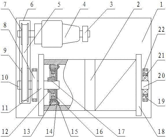
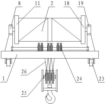
[0017] like figure 1 and figure 2 As shown in the figure, a portable electric trolley for a crane includes a trolley frame 1, the upper surface of the trolley frame 1 is provided with a roller 2, and the two ends of the roller 2 are respectively provided with a left end cover 11 and a right end cover Cover 18, the center of the left end cover 11 and the right end cover 18 are respectively provided with a support shaft A10 and a support shaft B20, the support shaft A10 and the support shaft B20 are respectively arranged on the left support 8 and the right support 19, The left support 8 and the right support 19 are arranged on the upper surface of the trolley 1, and the support shaft A10 is provided with a large synchronous toothed pulley 9, and the large synchronous toothed pulley 9 passes through. The toothed belt 5 is connected with a small synchronous toothed pulley 7, the small synchronous toothed pulley 7 is arranged on the output shaft of the motor 4, the brake 3 is con...

Embodiment 2

[0020] like figure 1 and figure 2 As shown in the figure, a portable electric trolley for a crane includes a trolley frame 1, the upper surface of the trolley frame 1 is provided with a roller 2, and the two ends of the roller 2 are respectively provided with a left end cover 11 and a right end cover Cover 18, the center of the left end cover 11 and the right end cover 18 are respectively provided with a support shaft A10 and a support shaft B20, the support shaft A10 and the support shaft B20 are respectively arranged on the left support 8 and the right support 19, The left support 8 and the right support 19 are arranged on the upper surface of the trolley 1, and the support shaft A10 is provided with a large synchronous toothed pulley 9, and the large synchronous toothed pulley 9 passes through. The toothed belt 5 is connected with a small synchronous toothed pulley 7, the small synchronous toothed pulley 7 is arranged on the output shaft of the motor 4, the brake 3 is con...


PUM


Abstract

The invention relates to a light electric trolley for a crane. The light electric trolley comprises a trolley frame. A roller is arranged on the upper surface of the trolley frame. A left end cover and a right end cover are arranged at the two ends of the roller respectively. A supporting shaft A and a supporting shaft B are arranged in the center of the left end cover and the center of the right end cover respectively and arranged on a left support and a right support respectively. The supporting shaft A is provided with a synchronous tooth-profile large belt wheel. The synchronous tooth-profile large belt wheel is connected with a synchronous tooth-profile small belt wheel through a tooth-profile belt, and the synchronous tooth-profile small belt wheel is arranged on an output shaft of a motor. A harmonic generator is arranged on the part, in the roller, of the supporting shaft A. A flexible wheel is arranged outside the harmonic generator. The outer circumference of the flexible wheel is connected with a rigid wheel in an engaged manner. The rigid wheel is fixedly connected to a supporting base through a bolt. A steel wire rope is wound on the outer wall of the roller and connected with a lifting hook assembly through a fixed pulley assembly, and a walking mechanism is arranged on the lower surface of the trolley frame. The light electric trolley is compact in structure, small in dead load, large in bearing capability and high in transmission efficiency.

Description

technical field [0001] The invention belongs to the technical field of cranes, in particular to an electric trolley, in particular to a portable electric trolley for cranes. Background technique [0002] In cranes, electric trolleys are mainly used to lift and move goods. Among them, the lifting mechanism is the most important and most basic mechanism in electric trolleys. Its structure type directly affects the size and weight of the crane trolley. Traditional In the electric trolleys used in beam-type and bridge-type cranes, the motor is parallel to the axis of the drum or the motor, the reducer and the drum are arranged in a straight line. Among them, the first arrangement is simple in design and easy to use, but it requires the trolley to It has sufficient strength and rigidity to increase the self-weight of the small frame, and the overall structure of each part on the small frame is loose, and the installation and adjustment are also more troublesome; the second arrang...

Claims


Application Information

Patent Timeline
Patent Type & Authority Applications(China)
IPC IPC(8): B66D1/12B66D1/20B66C11/00
Inventor 刘继伟王积贤崔丽胡哲涛
Owner HENAN SINOKO CRANES
Why Eureka
Try Eureka