Continuous sludge thermo-hydrolysis device and use method thereof

A technology for thermal hydrolysis and sludge, applied in chemical instruments and methods, mixers with rotary stirring devices, dewatering/drying/concentrating sludge treatment, etc., can solve the problem of large-scale application of sludge thermal hydrolysis process , insufficient stability, low treatment efficiency, etc., to achieve stable thermal hydrolysis effect of sludge, strong sludge adaptability, and sufficient sludge hydrolysis.

Inactive Publication Date: 2016-03-23
BEIJING JIELV ENVIRONMENTAL TECH CO LTD
View PDF6 Cites 4 Cited by
  • Summary
  • Abstract
  • Description
  • Claims
  • Application Information

AI Technical Summary

Problems solved by technology

This method is cumbersome to operate, not stable enough, and has low treatment efficiency, which is not conducive to the large-scale application of sludge thermal hydrolysis process.

Method used


Image

  • Continuous sludge thermo-hydrolysis device and use method thereof
  • Continuous sludge thermo-hydrolysis device and use method thereof
  • Continuous sludge thermo-hydrolysis device and use method thereof

Examples


Embodiment 1

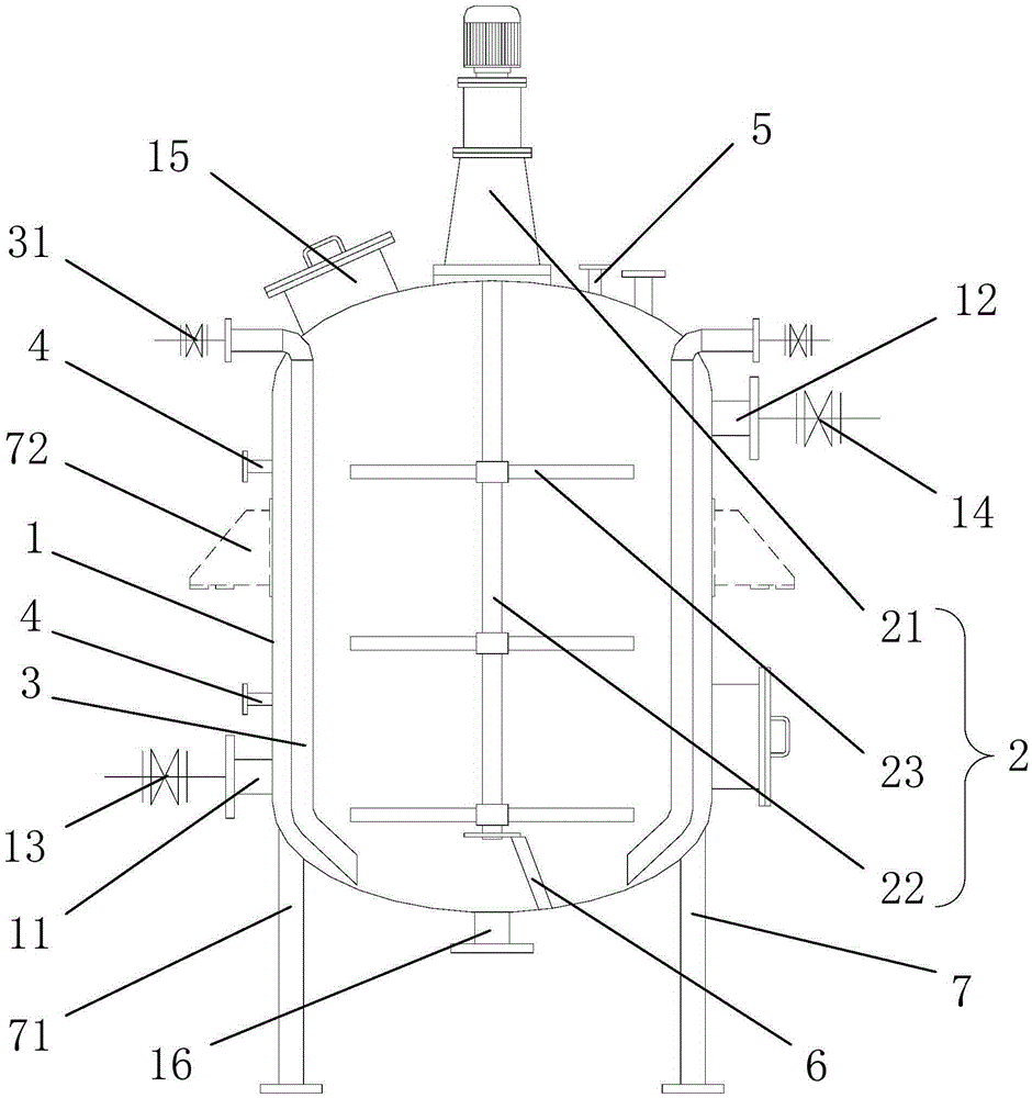
[0026] Such as figure 1 As shown, the continuous sludge thermal hydrolysis device provided in this embodiment includes a tank body 1, a stirring device 2, a steam pipeline 3, a temperature detection device 4 and a pressure detection device 5; wherein, the lower part of the side wall of the tank body 1 A feed port 11 is provided, a discharge port 12 is provided on the upper part of the side wall of the tank body 1, and a feed valve 13 and a discharge valve 14 are respectively provided at the feed port 11 and the discharge port 12; the stirring device 2 is arranged on In the tank body 1, it is used to mix the sludge and steam in the tank body 1 evenly; the steam pipe 3 penetrates into the tank body 1 from the top of the tank body 1, and extends down the inner wall of the tank body 1 to the bottom of the tank body 1 At the bottom, the entrance of the steam pipeline 3 is provided with a steam valve 31; the temperature detection device 4 is respectively arranged on the upper and lo...

Embodiment 2

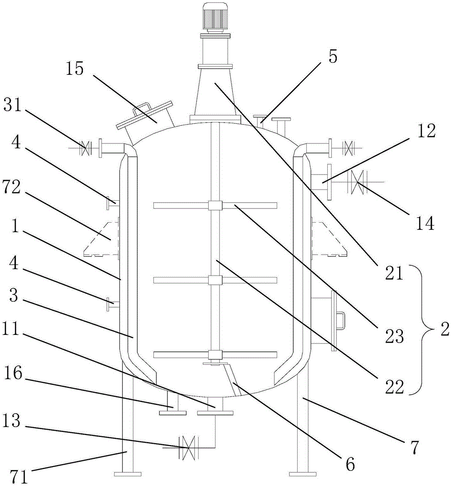
[0035] Such as figure 2 As shown, the structure of the continuous sludge thermal hydrolysis device provided in this embodiment is basically the same as that in Embodiment 1, the only difference being that the feed port 11 is arranged at the bottom of the tank body 1 in this embodiment.

Embodiment 3

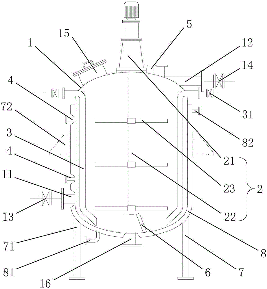
[0037] Such as image 3 As shown, the structure of the continuous sludge thermal hydrolysis device provided in this embodiment is basically the same as that of Embodiment 1, the only difference is that in this embodiment, a jacket 8 is provided outside the tank body 1, and the jacket 8 includes a steam inlet. 81 and steam outlet 82; when the temperature inside the tank body 1 does not reach the set temperature, high-temperature steam can be introduced into the jacket 8 to make the temperature inside the tank body 1 more stable and controllable. The whole process of hydrolysis provides a strong guarantee.


PUM


Abstract

The invention relates to a continuous sludge thermo-hydrolysis device and a use method thereof. The device comprises a tank body, a stirring device arranged in the tank body, a steam pipeline penetrating through the tank body from the top of the tank body and extending to the bottom of the tank body along the inner wall of the tank body, temperature detection devices arranged at the upper part and the lower part of the side wall of the tank body respectively and a pressure detection device arranged at the top of the tank body, wherein a feed port is formed in the bottom of the tank body or the lower part of the side wall of the tank body; a discharge outlet is formed in the upper part of the side wall of the tank body; a feed valve and a discharge valve are arranged at the feed port and the discharge outlet respectively; a steam valve is arranged at an inlet of the steam pipeline. According to the continuous sludge thermo-hydrolysis device, materials are fed into the tank body from the lower part of the tank body and discharged from the upper part of the tank body; the stirring device with multiple layers of paddles is arranged, the materials are continuously conveyed for thermo-hydrolysis treatment, the treatment process is simple, operation is convenient, the treatment efficiency is improved, and a new approach is provided for large-scale application of the sludge thermo-hydrolysis process.

Description

technical field [0001] The invention relates to a sludge environmental protection treatment device and a use method thereof, in particular to a continuous sludge thermal hydrolysis device and a use method thereof. Background technique [0002] With the rapid development of my country's economy, more and more wastewater needs to be treated, and the corresponding sludge production is gradually increasing. If these sludges are not handled properly, they will cause great harm to the environment; and people's awareness of environmental protection is getting stronger and stronger , so that the standard of environmental protection treatment is also gradually improved. [0003] Sludge is the product of sewage treatment, which is an extremely complex heterogeneous body composed of organic debris, bacterial cells, inorganic particles and colloids. The main characteristics of sludge are high water content (up to 99%), high content of organic matter, easy to rot and smell, and the parti...

Claims


Application Information

Patent Timeline
Patent Type & Authority Applications(China)
IPC IPC(8): C02F11/12B01F7/20B01F15/06B01F27/906
CPCC02F11/12B01F27/906B01F35/2113B01F35/2115B01F35/91B01F2035/99
Inventor 赵凤秋张锋吕东升景有海
Owner BEIJING JIELV ENVIRONMENTAL TECH CO LTD
Why Eureka
Try Eureka