Planetary rotor engine

A rotary engine and planetary technology, applied in combustion engines, machines/engines, internal combustion piston engines, etc., can solve problems such as low efficiency, unreasonable structure, and large weight, and achieve high efficiency, low mechanical vibration and wear, and power consumption. small effect

Inactive Publication Date: 2016-03-23
苗军
View PDF5 Cites 8 Cited by
  • Summary
  • Abstract
  • Description
  • Claims
  • Application Information

AI Technical Summary

Problems solved by technology

[0003] The purpose of the present invention is to provide a planetary rotor engine to overcome the defects of large volume, weight and low efficiency caused by the unreasonable structure of the reciprocating piston engine.

Method used


Image

  • Planetary rotor engine
  • Planetary rotor engine
  • Planetary rotor engine

Examples


Embodiment 1

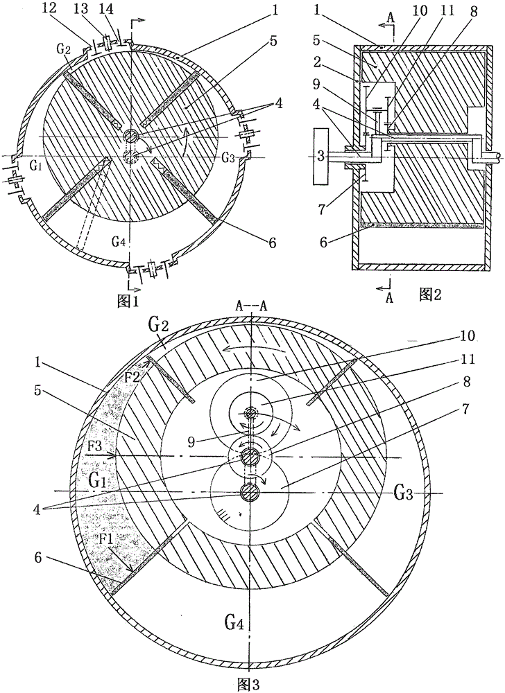
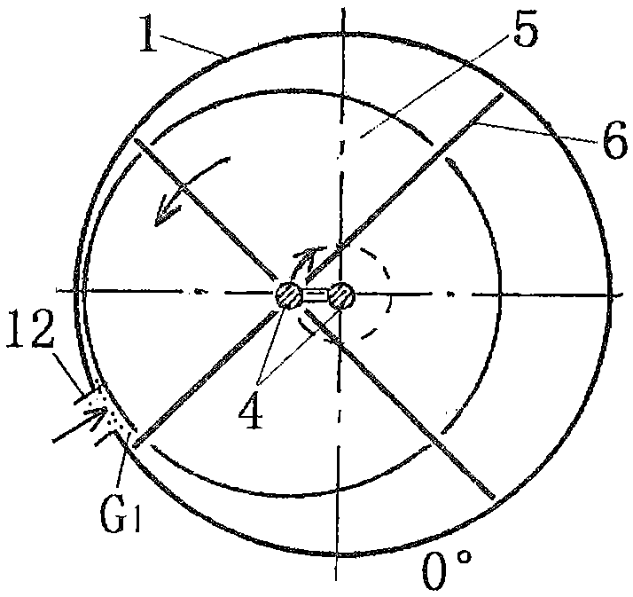
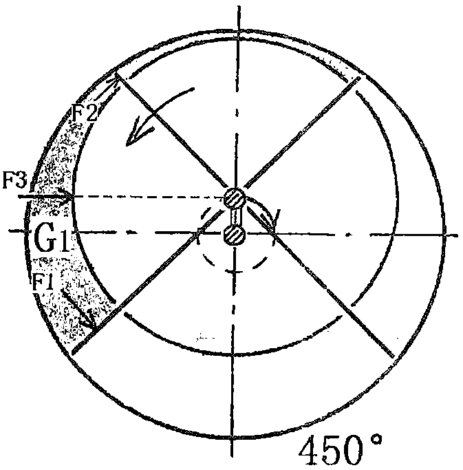
[0023] Such as figure 1 , 2 , 3, the planetary rotor engine of the present invention, the two ends of the tubular stator 1 are closed by the end cover 2, and the crankshaft 4 connecting the flywheel 3 is arranged inside, the main journals at the two ends of the crankshaft are supported at the center of the end cover, and the middle section of the crankshaft is The planetary journal and the support are equipped with a planetary column 5 for rotation fit. There are more than two radial slots on the planetary column. Each slot is inserted with a blade 6 for telescopic sliding and sealing fit. The inner side of the blade and the bottom of the groove Springs are interposed so that the outer side is close to the inner wall of the stator, and the left and right sides of the planetary column and blades are in sliding and sealing cooperation with the inner wall of the end cover. Each blade divides the inner cavity of the stator into a closed space with the same number of blades as the ...

Embodiment 2

[0035] Such as figure 1 As shown by the dotted line in the center, the slots on the planetary column 5 and the blades 6 are inclined in the radial direction, so that they are inclined to the inner wall of the stator 1, so as to reduce the pressure and friction caused by the centrifugal force of the blades on the inner wall of the stator.

Embodiment 3

[0037] Such as Figure 16 As shown, the end cap on one side has a groove to accommodate the crank arm and gear train, and the end cap on the other side has a groove to accommodate the other crank arm.


PUM


Abstract

The invention discloses a planetary rotor engine. Crankshafts (4) are arranged in a cylindrical stator (1) of the planetary rotor engine, and the two ends of the cylindrical stator (1) are sealed through end covers. Main shaft necks at the two ends of the cylindrical stator (1) are supported in the centers of the crankshafts (4), and planetary columns (5) are supported on planetary shaft necks in the middle sections of the crankshafts (4). A set of telescopic blades (6) are inserted in each planetary column in the radial direction. The planetary columns and the left sides and the right sides of the blades are in sliding and sealing fit with the inner walls of the end covers, the outer sides of the blades and the inner wall of the stator. An inner cavity of the stator is divided into a set of cylinders by the blades. The planetary columns rotate in the opposite direction while revolving around the axis of the stator, so that the volumes of the cylinders are increased and decreased periodically, and the strokes including air suction, compression, acting and exhausting are completed in sequence. Fuel gas expands to push the blades and the planetary columns to act in pairs, so that the acting torque is increased; the cylinders are densely arranged, so that the power is sufficient; the rotating direction is opposite to the revolving direction, so that the speed, relative to fixed part, of moving parts is low, and the friction between the moving parts and the fixed part is small.

Description

[0001] Technical Field: The present invention relates to an engine, in particular to a planetary rotor engine. Background technique [0002] The reciprocating piston engine has many reciprocating parts, plus a heavy crank-link mechanism, which makes it have large harmful inertia, bulky parts, high power consumption, large vibration, and fast wear. Through extensive searches, no technical solutions identical to the present invention have been found. Contents of the invention [0003] The object of the present invention is to provide a planetary rotor engine for overcoming the defects of large volume, heavy weight and low efficiency caused by unreasonable structure of the reciprocating piston engine. [0004] The technical solution adopted by the present invention to solve its technical problems is: [0005] A planetary rotor engine, characterized in that: the two ends of the cylindrical stator are closed by the end cover, and the crankshaft connected to the flywheel is arran...

Claims


Application Information

Patent Timeline
Patent Type & Authority Applications(China)
IPC IPC(8): F02B53/00F02B55/02F02B55/08
CPCF02B53/00F02B55/02F02B55/08F02B2730/012Y02T10/12
Inventor 苗军
Owner 苗军
Why Eureka
Try Eureka