Integrated imaging optical system
An optical system and integrated imaging technology, which is applied in the field of optical systems and integrated imaging optical systems, can solve the problems of small depth areas of reconstructed images and constraints on the commercialization of integrated imaging 3D displays, etc.
- Summary
- Abstract
- Description
- Claims
- Application Information
AI Technical Summary
Problems solved by technology
Method used
Image

Examples
Embodiment 1
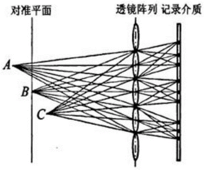
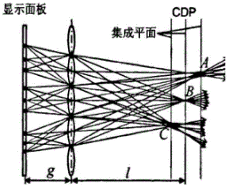
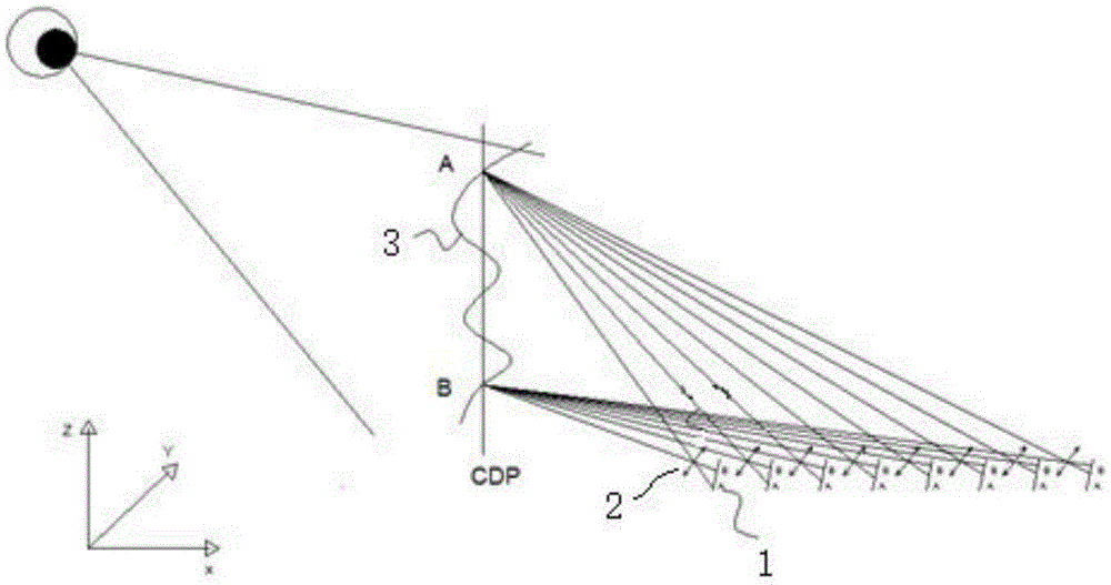
[0058] The present invention analyzes the relationship between the imaging point in space and the physical display array through the pinhole imaging model, and proposes a design structure of a micro-optical system, which can realize that the central depth plane (CDP) is perpendicular to the physical display plane and forms a real image The floating display effect has a strong sense of technology and future. In addition, the 360-degree full-view 3D display can be realized by splicing and displaying, which effectively reduces the amount of data required to realize complex 3D scenes. And effectively eliminate the fatigue of human eyes watching.
[0059] When integrated imaging reproduces a 3D scene, there is only one image plane that is conjugate to the display panel. When the image plane of the reproduced 3D image deviates from this plane, the resolution will drop significantly. The plane that is conjugate with the display panel is called the Central Depth Plane (CDP for short)...
Embodiment 2
[0072] This technical solution realizes the formation of a real image of a two-dimensional floating display perpendicular to the horizontal plane in space. The structure of the optical components is as follows: Figure 14 As shown, in this embodiment, the micro-image array is placed on a wedge-shaped glass substrate with an inclination angle of ω, the plane formed by the micro-image unit array forms a small angle ω with the horizontal plane, and the plane formed by the micro-image unit and the micro-image unit array is The angle between them is 0, the micro-optical unit array is set as a plane, parallel to the horizontal plane and placed on the micro-image array in reverse, and a group of micro-ray refraction units are placed above the optical unit array to change the image through the lens. The direction of light propagation after modulation. In this embodiment, the micro-optical unit is preferably used as a lens, and the micro-image array adopts an ultra-high-resolution liqu...
Embodiment 3
[0078] This technical solution realizes the formation of a two-dimensional suspended real image perpendicular to the display plane in space. The micro-optical unit is a concave mirror array, which adopts a one-dimensional lens array arranged at non-equal intervals, and metal Al is evaporated on the surface of the lens as a reflector. layer, so that the lens array becomes a concave mirror array, such as Figure 17 As shown, there are m unit concave mirrors on each one-dimensional concave mirror.
[0079] In this embodiment, a transparent OLED display is preferably selected as the micro-image unit array, and the one-dimensional OLED display array is attached to the one-dimensional concave mirror array. Place n groups of such one-dimensional concave mirror arrays (as reflective layer 40) bonded with OLED displays in the base engraved with n inclined grooves, so that the plane of the OLED display array is parallel to the horizontal plane, and the focal plane of the concave mirrors...
PUM
 Abstract
Description
Claims
Application Information
 - R&D
- Intellectual Property
- Life Sciences
- Materials
- Tech Scout
- Unparalleled Data Quality
- Higher Quality Content
- 60% Fewer Hallucinations
Browse by: Latest US Patents, China's latest patents, Technical Efficacy Thesaurus, Application Domain, Technology Topic, Popular Technical Reports.
© 2025 PatSnap. All rights reserved.Legal|Privacy policy|Modern Slavery Act Transparency Statement|Sitemap|About US| Contact US: help@patsnap.com