Supercharge Your Innovation With Domain-Expert AI Agents!

Polarization beam splitting device for sequential laser laser shadow photography

A polarization beam splitting device, laser shadow technology, applied in optics, photography, optical components, etc., can solve problems such as unfavorable multi-sequence imaging, and achieve the effects of reducing circle diameter, improving coincidence, and reducing stray light

Active Publication Date: 2019-02-01
中国空气动力研究与发展中心超高速空气动力研究所
View PDF7 Cites 0 Cited by
  • Summary
  • Abstract
  • Description
  • Claims
  • Application Information

AI Technical Summary

Problems solved by technology

When the multi-sequence laser shadow photography system is imaging the test area, the information of the area that does not completely overlap will be lost when it is imaged in different sequences. Therefore, the smaller the overlap of the test area, the more the test information will be lost, which is not conducive to multi-sequence imaging

Method used


Image

  • Polarization beam splitting device for sequential laser laser shadow photography
  • Polarization beam splitting device for sequential laser laser shadow photography
  • Polarization beam splitting device for sequential laser laser shadow photography

Examples


Embodiment 1

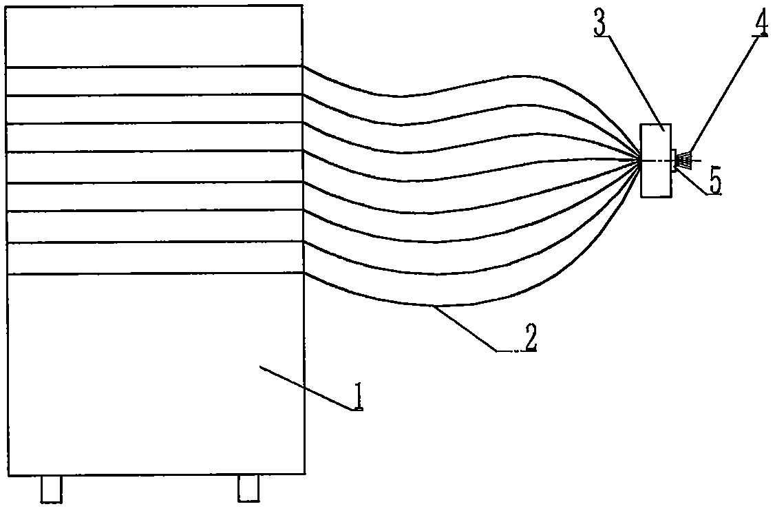
[0020] Such as figure 1 As shown, the sequence of light beams emitted by the light source system 1 enters the multi-light source space separation device 3 through the optical fiber 2. The multi-light source space separation device 3 is equipped with a multi-light source space separation disc 5 at the front end, and the output ends of the multiple optical fibers are located on the multi-light source space separation disc. 5 and distributed evenly.

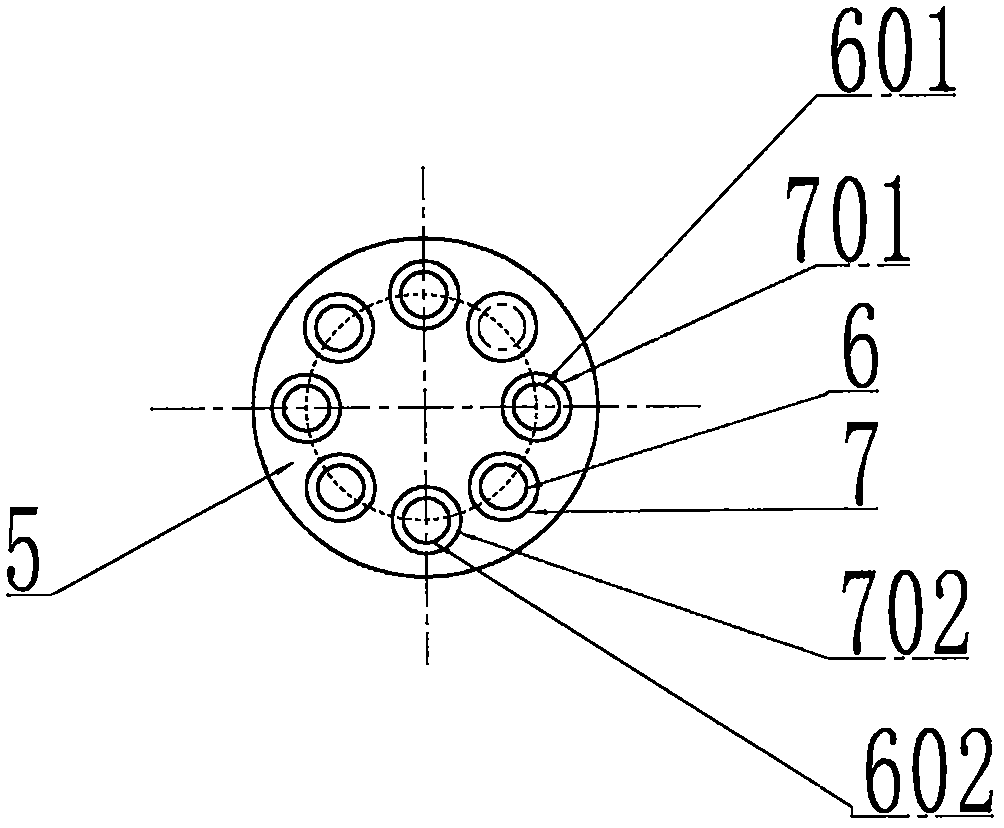
[0021] figure 2 It is an enlarged side view of the multi-light source space separation disc 5. The beams emitted from the output ends of multiple optical fibers are not expanded to form a plurality of focal spots 6. The larger the diameter of the circle occupied by each focal spot 6, the more favorable it is for multi-sequence lasers. The spectroscopic device of the imaging system in the shadow photography system splits light beams in different sequences, but the larger the diameter of the circle, the smaller the degree of coincid...


PUM


Abstract

The invention belongs to the field of ultra-high-speed transient imaging, and relates to a polarization beam splitting device for sequential laser shadow photography, including a polarizing device and a polarization beam splitting device. The components of the device include a polarizer, a polarizing sleeve, a first optical protection glass, a second optical protection glass and a protection sleeve. The present invention utilizes the principle that polarizers can only transmit light that is consistent with the polarization direction. In the multi-sequence laser shadow photography system, the polarization characteristics of different sequences of laser beams that come out of the multi-sequence laser shadow photography system through the multi-light source space separation device have disappeared, and come out through the multi-light source space separation device. A polarizer is placed at the position of the focal spot of the beam, and the polarization direction of the beam passing through the polarizer is consistent with the polarization direction of the polarizer, and the polarization directions of the polarizers placed by different sequences of beams are sequentially different by 90°.

Description

technical field [0001] The invention belongs to the field of ultra-high-speed transient imaging, and relates to a polarization beam splitting device for sequential laser shadow photography. Background technique [0002] With the development of my country's aerospace technology, weapons and equipment, and basic disciplines, research in the fields of ultra-high-speed aerodynamics, ultra-high-speed collisions, explosions and impacts, combustion and chemical reactions has continued to deepen. In these research works, many phenomena are ultra-high-speed transient change processes with a duration of only microseconds or even nanoseconds. It is necessary to have a camera system that can clearly and continuously image and record this process in order to grasp the physical phenomena. Nature. In addition to requiring the amplitude and frequency to reach 10 million frames per second (that is, the shortest exposure and imaging time is 100ns), this camera system can perform sequential i...

Claims


Application Information

Patent Timeline
Patent Type & Authority Patents(China)
IPC IPC(8): G03B15/05G03B39/00G02B27/28
CPCG02B27/283G03B15/05G03B39/00
Inventor 谢爱民黄洁宋强文雪忠柯发伟李晶郑蕾柳森
Owner 中国空气动力研究与发展中心超高速空气动力研究所
Features
  • R&D
  • Intellectual Property
  • Life Sciences
  • Materials
  • Tech Scout
  • Unparalleled Data Quality
  • Higher Quality Content
  • 60% Fewer Hallucinations
Learn More