Voltage control circuit and method, grid driving circuit, and display apparatus

A technology of voltage control circuit and capacitor control, applied in the fields of voltage control circuit, gate drive circuit and display device, can solve the problems of poor process compatibility, large reverse cut-off gate-source voltage, etc., and achieves the improvement of process compatibility. Effect

Active Publication Date: 2016-03-23
BOE TECH GRP CO LTD +1
View PDF3 Cites 23 Cited by
  • Summary
  • Abstract
  • Description
  • Claims
  • Application Information

AI Technical Summary

Problems solved by technology

[0003] The main purpose of the present invention is to provide a voltage control circuit, a method, a gate drive circuit and a display device, which solve the problem of poor process compatibility in the prior art when solving the problem of high-temperature abnormal display caused by a large reverse cut-off gate-source voltage The problem

Method used


Image

  • Voltage control circuit and method, grid driving circuit, and display apparatus
  • Voltage control circuit and method, grid driving circuit, and display apparatus
  • Voltage control circuit and method, grid driving circuit, and display apparatus

Examples


no. 2 Embodiment

[0146] Compared with the second specific embodiment, the third specific embodiment of the voltage control circuit of the present invention has been further optimized, and its characteristic is to introduce the first control capacitor C1 and the second control capacitor C2 with equal capacitance values, and adopt CLK and CLKB replace Vdd, reducing a Vdd signal source and adding an implementation method; CLK is responsible for charging C1 and C2; the gate voltage of MF is controlled by C2.

[0147] When the third specific embodiment of the voltage control circuit of the present invention works, as Figure 13 as shown,

[0148] In the preparation period T0 of each display cycle, CLKB is at high level, CLK and CLK' are at low level, MC2 and MC3 are both off, and there is no loop formed between C1 and C2, so C1 and C2 are not charged, and MF is off. open;

[0149] In the output period T1 of each display cycle, CLK and CLK' are high level, CLKB is low level, MC2 and MC3 are both t...


PUM


Abstract

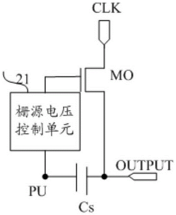
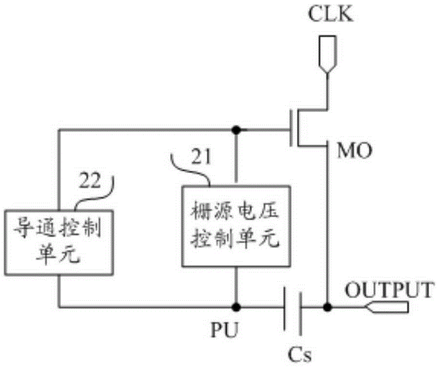
The invention provides a voltage control circuit and method, a grid driving circuit, and a display apparatus. The voltage control circuit comprises a grid source voltage control unit which is connected with a grid of an output transistor and an upper-drawing node for controlling grid source voltage of the output transistor to be smaller than preset grid source voltage through controlling grid level of the output transistor when level of the upper-drawing node is low in an output cut-off maintenance time period of each display period, wherein the preset grid source voltage is smaller than or equal to zero. All transistors included by the grid source voltage control unit are n-type transistors. In each display period, the output cut-off maintenance time period is set after an output time period. All the transistors included in the grid source voltage control unit included by the voltage control circuit provided by the invention are all n-type transistors. The voltage control circuit can improve the technical compatibility while solving the problem of high-temperature abnormal display caused by too large reverse cut-off grid source voltage.

Description

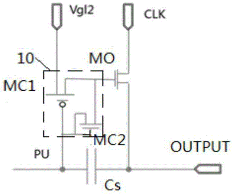
technical field [0001] The invention relates to the field of display technology, in particular to a voltage control circuit, a method, a gate drive circuit and a display device. Background technique [0002] In the traditional GOA (GateOnArray, array substrate row drive) circuit design, in the output cut-off hold stage (that is, the stage after outputting a high-level gate drive signal), the gate potential of the output transistor is -8V. The potential of the drive signal output terminal is also -8V, so the gate-source voltage of the output transistor is 0V during the output cut-off and hold stage, and abnormal display will be caused by a large leakage current in a high-temperature environment. Such as figure 1 As shown, the existing voltage control circuit uses a NAND gate 10 to control the gate-source voltage of the output transistor MO to be less than 0 during the output cut-off and hold phase, that is, to control the reverse control when the potential of the pull-up nod...

Claims


Application Information

Patent Timeline
Patent Type & Authority Applications(China)
IPC IPC(8): G09G3/20
CPCG09G3/20G09G3/3266G09G3/3677G09G2310/0267G09G2310/0286G09G2310/08G11C19/28G09G3/2014
Inventor 王俊伟
Owner BOE TECH GRP CO LTD
Why Eureka
Try Eureka