
Distribution network loop closing power supply switching method

A technology of ring rotation and distribution network, which is applied in the direction of AC network circuit, protection against overcurrent, electrical components, etc., and can solve the problems of inability to accurately reflect real-time changing operating conditions, complex modeling and simulation verification, and blackout area Expansion and other issues to achieve the effect of improving power supply reliability, easy access to data, and reducing power outage losses

Active Publication Date: 2016-03-23
HONGHE POWER SUPPLY BUREAU OF YUNNAN POWER GRID
View PDF5 Cites 13 Cited by
  • Summary
  • Abstract
  • Description
  • Claims
  • Application Information

AI Technical Summary

Problems solved by technology

Improper loop closing operation will generate excessive loop closing current, resulting in tripping of the protection action and expanding the blackout area
The existing distribution network non-stop power supply technology is not complete, generally requires complex modeling and simulation verification, and different operating conditions often require different verification, or add more equipment to obtain measurement data at loop closure points, or perform complex power flow calculations
Moreover, the power flow in the loop changes before and after the loop is closed, and it is difficult to directly calculate the size of the circulation with a simple formula, which cannot accurately reflect the real-time changing operating conditions

Method used


Image

  • Distribution network loop closing power supply switching method
  • Distribution network loop closing power supply switching method
  • Distribution network loop closing power supply switching method

Examples


Embodiment

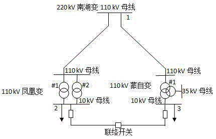
[0055] Example: Take the two 10kV connecting lines of the 110kV Mengzi Substation and the 110kV Fenghuang Substation of the Honghe Power Grid as an example, as figure 2 As shown, the power points of the two 110kV substations are both from the 110kV busbar of the 220kV Nanhu Substation, the 110kV Phoenix becomes two two-column substations running in parallel, and the 110kV Mengzi becomes two three-column substations running in parallel (#2 main transformer is omitted Drawing), 10kV line is YJV22-3×300 cable.

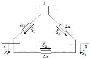
[0056] After the 10kV line is closed, an electromagnetic ring network is formed under the condition of no-load on the 35kV side of the main transformer #1 of Mengzi substation. The simplified equivalent circuit, such as image 3 As shown, the flow through the impedance

[0057] The complex power of , that is, the complex power flowing to the buses on both sides of the tie switch is:

[0058] (1)

[0059] (2)

[0060] Well, flow through The complex power of i...


PUM


Abstract

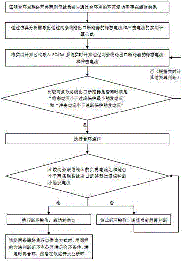
The invention discloses a distribution network loop closing power supply switching method. The method comprises the following steps: proving that a linear relation exists between bus load on two sides of a loop closing point interconnection switch and loop current complex power of a loop closing point through analysis; deriving a practical calculation formula of a steady-state current and an impact current of an interconnection line outlet circuit breaker through simulation; introducing the practical calculation formula into an SCADA system; calculating the steady-state current and the impact current of the interconnection line outlet circuit breaker, and calculating the sum of load currents of two interconnection lines; then comparing with related data, and judging whether the operations of loop closing, loop disconnecting and power supply switching can be performed accordingly. The method disclosed by the invention is simple and practical, data are easily acquired, and equipment does not need to be added, so that complicated complex operation is avoided, the method is easy to implement, higher in precision and accuracy and lower in error, a powerful basis can be provided for the distribution network loop closing power supply switching operation of a power dispatcher, the power distribution reliability is effectively improved, the outage cost is reduced, and the method has extremely high application values.

Description

technical field [0001] The invention relates to the technical field of distribution network closure, in particular to an operation method for distribution network closure and loop switching power supply. Background technique [0002] With the rapid development of the economy, the requirements for the reliability of power supply are getting higher and higher. The hand-in-hand two-way power supply method in the distribution network improves the reliability of power supply in the form of grid structure, but the traditional power failure to power supply still has short-term power failure. , breaking the continuity of power supply, and switching power supply without power outage has become an effective way to improve the reliability of power supply. Improper loop closing operation will generate excessive loop closing current, resulting in tripping of the protection action and expanding the blackout area. The existing distribution network non-stop power supply technology is not c...

Claims


Application Information

Patent Timeline
IPC IPC(8): H02J3/00H02J9/02H02H3/08
CPCH02H3/08H02J3/0073H02J9/02H02J2203/20
Inventor 张磊时雨陈志坚
Owner HONGHE POWER SUPPLY BUREAU OF YUNNAN POWER GRID
Learn More