
Identification method for rotating speed of permanent magnet synchronous motor

A permanent magnet synchronous motor and identification method technology, applied in the field of permanent magnet synchronous motor control and permanent magnet synchronous motor speed identification, can solve the problem of difficult real-time and accurate identification of motor speed, and achieve simple structure, good real-time performance, and computational complexity. small effect

Active Publication Date: 2016-03-23
HI HLDG
View PDF3 Cites 0 Cited by
  • Summary
  • Abstract
  • Description
  • Claims
  • Application Information

AI Technical Summary

Problems solved by technology

[0005] The purpose of the present invention is to solve the problem that the motor speed is difficult to identify accurately in real time in the closed-loop control of the permanent magnet synchronous motor, and propose a method for identifying the speed of the permanent magnet synchronous motor

Method used


Image

  • Identification method for rotating speed of permanent magnet synchronous motor
  • Identification method for rotating speed of permanent magnet synchronous motor
  • Identification method for rotating speed of permanent magnet synchronous motor

Examples


Embodiment Construction

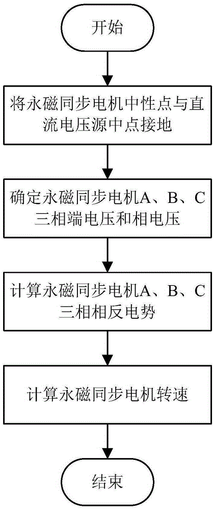
[0022] Such as figure 1 As shown, it is a method for identifying the rotational speed of a permanent magnet synchronous motor according to the present invention, which includes the following steps:

[0023] (1) Ground the neutral point of the permanent magnet synchronous motor and the midpoint of the DC voltage source, thereby clamping the voltage of the neutral point of the permanent magnet synchronous motor to 0;

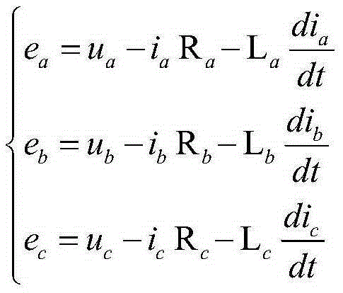
[0024] (2) Determine the terminal voltage of the permanent magnet synchronous motor through the conduction process of the three-phase full-bridge inverter and the on-off state of the power tube and the freewheeling diode in the freewheeling process; subtract the neutral point from the terminal voltage The voltage of the permanent magnet synchronous motor is obtained;

[0025] When determining the terminal voltages of the three phases A, B, and C of the permanent magnet synchronous motor, the two conditions of the conduction process and the freewheeling process of...


PUM


Abstract

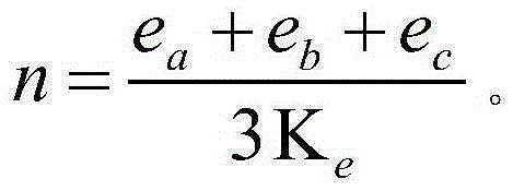
The invention discloses an identification method for a rotating speed of a permanent magnet synchronous motor. The method comprises the steps as follows: a neutral point of the permanent magnet synchronous motor and a midpoint of a direct current voltage source are grounded, so that a voltage of the neutral point of the permanent magnet synchronous motor is zero; a terminal voltage of the permanent magnet synchronous motor is determined through on-off states of a power tube and a free-wheeling diode in a conduction process and a fly-wheeling process of a three-phase full-bridge inverter and the voltage of the neutral point is subtracted from the terminal voltage, so as to obtain a phase voltage of the permanent magnet synchronous motor; a three-phase counter electromotive force of the permanent magnet synchronous motor is calculated by the phase voltage and a phase current, detected through a current sensor, of the permanent magnet synchronous motor according to a phase voltage balance equation of the permanent magnet synchronous motor; and the rotating speed of the permanent magnet synchronous motor is calculated by the three-phase counter electromotive force of the permanent magnet synchronous motor and a counter electromotive force coefficient of the motor. The identification method is few in required motor parameters, simple in structure, small in calculated quantity, high in identification accuracy and good in real time.

Description

technical field [0001] The invention relates to a permanent magnet synchronous motor, in particular to a method for identifying the rotational speed of a permanent magnet synchronous motor, and belongs to the field of permanent magnet synchronous motor control. Background technique [0002] The permanent magnet synchronous motor has many advantages such as simple structure, high power density, and simple control. In recent years, permanent magnet synchronous motors have been increasingly widely used in industrial fields such as high-performance speed regulation systems and servo control systems. [0003] In the closed-loop control of permanent magnet synchronous motor, the identification of the speed has an important influence on the stable operation of the motor. If the speed identification is inaccurate, it will lead to poor speed regulation accuracy of the permanent magnet synchronous motor, poor servo effect, and in severe cases, the permanent magnet synchronous motor w...

Claims


Application Information

Patent Timeline
IPC IPC(8): H02P6/00H02P21/18
CPCH02P6/00
Inventor 魏海峰韦汉培
Owner HI HLDG
Learn More