Field weakening control method for direct-drive permanent magnet generator
A permanent magnet generator and field weakening control technology, applied in synchronous generator control, generator control through magnetic field changes, power management and other directions, can solve the problems of complex synchronous motor field weakening control methods, etc. Simple process and low computational cost
- Summary
- Abstract
- Description
- Claims
- Application Information
AI Technical Summary
Problems solved by technology
Method used
Image
Examples
Embodiment 1
[0039] As a basic embodiment of the present invention, the present invention includes a field weakening control method for a direct-drive permanent magnet generator, including a machine-side rotor flux linkage orientation step and a reactive current given value calculation. Wherein, the calculation of the given value of reactive current specifically includes the following steps:
[0040] S 21 . Orient the d and q-axis rotor flux linkages in the two-phase rotating coordinate system obtained through the rotor flux linkage orientation step on the machine side, and lock the phases to obtain the frequency.
[0041] S 22 . Calculate impedance and related intermediate values;
[0042] S 23 .According to the steady-state field weakening control equation of the permanent magnet synchronous motor in the rotating coordinate system, the upper and lower limit values of the torque converted by reactive power are calculated, and the given value of reactive current is obtained.
Embodiment 2
[0044] As a preferred embodiment of the present invention, the present invention includes a field weakening control method for a direct-drive permanent magnet generator, including a machine-side rotor flux linkage orientation step and a reactive current given value calculation.
[0045] Wherein, the machine-side rotor flux linkage orientation step specifically includes the following steps:
[0046] S 11 .Convert the three-phase line voltage and current of the stator into the instantaneous voltage and current values in the two-phase stationary coordinate system;
[0047] S 12 . From the instantaneous value of voltage and instantaneous value of current in the two-phase static coordinate system, the α and β-axis rotor flux linkages in the two-phase static coordinate system are estimated by the mathematical model of the permanent magnet synchronous generator in the two-phase static coordinate system;
[0048] S 13 . Perform coordinate rotation transformation on rotor flux lin...
Embodiment 3
[0054] As the best mode for carrying out the present invention, refer to the appendix of the specification. figure 1 The invention includes a field weakening control method for a direct-drive permanent magnet generator, which includes a machine-side rotor flux linkage orientation step and a calculation of a given limit value of reactive current.
[0055] Wherein, the machine-side rotor flux linkage orientation step specifically includes the following steps:
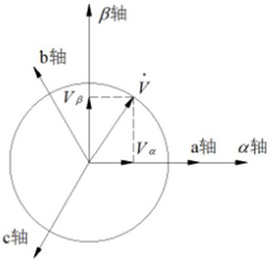
[0056] S 11 .The three-phase line voltage of the stator v ab (t), v bc (t), v ca (t) is converted into the instantaneous value u of the voltage in the two-phase stationary coordinate system α , u β , the three-phase current i of the stator a (t), i b (t), i c (t) is converted into the instantaneous value i of the current in the two-phase stationary coordinate system α , i β . in,
[0057]
[0058]
[0059] S 12 . From the instantaneous voltage and current values in the two-phase static coordinate syst...
PUM
 Abstract
Description
Claims
Application Information
 - R&D
- Intellectual Property
- Life Sciences
- Materials
- Tech Scout
- Unparalleled Data Quality
- Higher Quality Content
- 60% Fewer Hallucinations
Browse by: Latest US Patents, China's latest patents, Technical Efficacy Thesaurus, Application Domain, Technology Topic, Popular Technical Reports.
© 2025 PatSnap. All rights reserved.Legal|Privacy policy|Modern Slavery Act Transparency Statement|Sitemap|About US| Contact US: help@patsnap.com


