
Low-pressure two-bag self-suction tracheal catheter and use method thereof

A tracheal intubation and self-suction technology, which can be used in tracheal intubation, respirators, other medical devices, etc., can solve problems such as atelectasis, inability to directly attract secretions, and bronchial blockage, and achieve the effect of preventing ischemic necrosis.

Inactive Publication Date: 2016-03-30
夏敏
View PDF6 Cites 1 Cited by
  • Summary
  • Abstract
  • Description
  • Claims
  • Application Information

AI Technical Summary

Problems solved by technology

However, secretions in the trachea from the glottis to the endotracheal tube balloon cannot be directly aspirated
Every time before the endotracheal tube is pulled out, the air bag needs to be evacuated. When the air bag is evacuated, the secretions in the trachea above the air bag will instantly flow into the trachea below the air bag. Tube suction, but can not be completely sucked, unsuctioned secretions flow into the deep trachea or even into the bronchi, which may cause bronchial blockage, atelectasis, lung infection, etc., seriously affecting the prognosis of patients

Method used


Image

  • Low-pressure two-bag self-suction tracheal catheter and use method thereof
  • Low-pressure two-bag self-suction tracheal catheter and use method thereof
  • Low-pressure two-bag self-suction tracheal catheter and use method thereof

Examples


Embodiment Construction

[0020] The embodiments of the present invention will be described in detail below with reference to the accompanying drawings, but the present invention can be implemented in many different ways defined and covered by the claims.

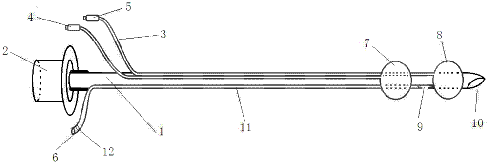
[0021] Such as Figure 1 ~ Figure 4 As shown, the present invention discloses a low-pressure double-bag self-suction tracheal catheter, including a tracheal catheter 1, a tracheal catheter interface 2, a balloon inflation tube 3, an upper balloon 7, a lower balloon 8, an upper balloon inflation valve 4, and a lower balloon inflation valve 5 And the suction tube 11, the endotracheal tube interface 2 is connected to the endotracheal tube 1, the upper air bag 7 and the lower air bag 8 are connected to an air bag inflation tube 3, and the upper air bag inflation valve 4 and the lower air bag inflation valve 5 are respectively connected to the air bag inflation tube 3 , the upper air bag inflation valve 4 and the lower air bag inflation valve 5 respectiv...


PUM


Abstract

The invention discloses a low-pressure two-bag self-suction tracheal catheter. The low-pressure two-bag self-suction tracheal catheter comprises a tracheal catheter body, a tracheal catheter connecting port, an air bag inflation tube, an upper air bag, a lower air bag, an upper air bag inflation valve, a lower air bag inflation valve and a suction tube. The tracheal catheter connecting port is connected to the tracheal catheter body. The upper air bag and the lower air bag are both connected with the air bag inflation tube. The air bag inflation tube is connected with the upper air bag inflation valve and the lower air bag inflation valve. The upper air bag and the lower air bag are arranged at the tail end of the tracheal catheter body. The upper air bag is arranged above the lower air bag. A suction tube opening is arranged above the lower air bag. The suction tube extends upwards to the upper end of the tracheal catheter body through the inner wall of the tracheal catheter body and penetrates out of the tracheal catheter body to be connected with a suction tube connecting port, and a sealed opening is formed in the tail end of the suction tube connecting port. The low-pressure two-bag self-suction tracheal catheter is ingenious in structure; by inflating the upper air bag and the lower air bag alternately, compression of the air bags to the inner wall of the trachea is relieved, and avascular necrosis of trachea mucosa is prevented; besides, before the lower air bag is deflated, secreta in the trachea above the lower air bag can be sucked cleanly through the suction tube, so that pulmonary infection caused when the secreta flows into the lower respiratory tract is prevented.

Description

technical field [0001] The invention relates to the field of medical auxiliary tools, in particular to a low-pressure double-bag self-suction tracheal catheter and a method for using the same. Background technique [0002] There are two important problems with existing single-lumen endotracheal tubes: [0003] First of all, the existing single-lumen endotracheal tube usually only has a single air bag. When the endotracheal tube inflates the air bag on the endotracheal tube, the air bag has the functions of fixing the endotracheal tube, sealing and preventing air leakage. However, when the air bag is inflated, the air bag will compress the tracheal mucosa, and long-term compression will lead to ischemia and necrosis of the tracheal mucosa, resulting in later softening, collapse or stenosis of the trachea, resulting in serious adverse consequences. Therefore, clinically, it is often necessary to deflate the airbag once every 4 to 6 hours after the airbag is inflated, for 5 to...

Claims


Application Information

Patent Timeline
Patent Type & Authority Applications(China)
IPC IPC(8): A61M16/04
CPCA61M16/0463A61M16/0003A61M16/0461A61M2210/1025
Inventor 夏敏
Owner 夏敏
Learn More