Wire rod edge cooling device and wire rod edge cooling method

A technology of cooling device and cooling method, which is applied in workpiece surface treatment equipment, metal rolling, manufacturing tools, etc., can solve the problems such as failure to achieve uniform temperature effect, short residence time of coil wire, limited temperature drop of coil wire, etc. Improve the effect of carbon and oxidation problems, ensure the temperature of the same circle in the phase change zone, uniform and stable product performance

Active Publication Date: 2016-03-30
BAOSHAN IRON & STEEL CO LTD
View PDF8 Cites 13 Cited by
  • Summary
  • Abstract
  • Description
  • Claims
  • Application Information

AI Technical Summary

Problems solved by technology
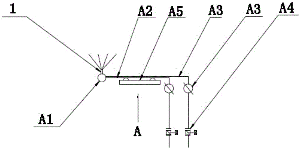
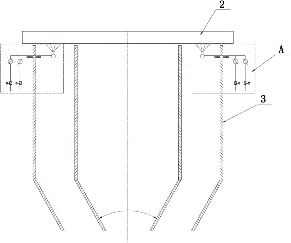
[0009] However, in the actual application process of this invention, due to factors such as the roller table section set up in the production line, there are the following problems: due to the cooling method of spraying air mist from the upper direction of the roller table, it can only be installed between the laying machine and the first The cooling length of the 2-3m long roller table section between the fans is limited and the coil wire stays in this position for a very short time, only 2-5 seconds, which makes the temperature drop of the coil wire at 900°C limited and cannot reach To achieve the desired temperature uniformity effect, and the length of the follow-up cooling roller table is nearly 100m, so there is still the current situation of uneven cooling at the coil side and the center on the follow-up cooling roller table, and the phase change completion area is just in this area, so this invention has a great impact on Reduce the temperature difference in the same circle and improve the strength difference in the same circle.
[0011] In summary, in order to solve the problem of cooling the edge of the coil wire in the prior art, a new type of cooling device and cooling method is urgently needed to solve the problem of cooling the edge of the coil wire, and can solve the problem of cooling the edge of the coil wire in the prior art. Due to structural limitations, the cooling range is small, the temperature drop is limited, the temperature is uneven, and the temperature difference between the same circle is reduced, and the strength difference of the same circle is limited to improve the problem.

Method used


Image

  • Wire rod edge cooling device and wire rod edge cooling method
  • Wire rod edge cooling device and wire rod edge cooling method
  • Wire rod edge cooling device and wire rod edge cooling method

Examples


Embodiment 1

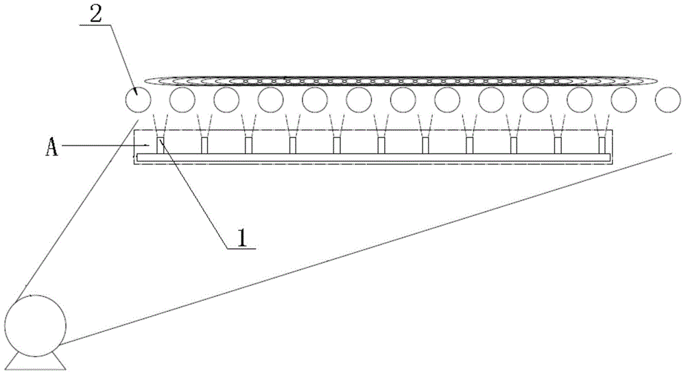
[0062] Example 1: For wire rod, the spinning temperature is 900°C, using 3 sets of edge cooling devices, each set of 30 nozzles on one side, the water pressure is 3bar, the air pressure is 5bar, and the measured temperature difference in the same circle is 47°C;

Embodiment 2

[0063] Example 2: For wire rod, the spinning temperature is 920°C, 5 sets of edge cooling devices are used, each set of 30 nozzles on one side, the water pressure is 1.5 bar, the air pressure is 3 bar, and the measured temperature difference in the same ring is 53°C;

Embodiment 3

[0064] Example 3: For wire rod, the spinning temperature is 880°C, using 5 sets of edge cooling devices, each set of 30 nozzles on one side, the water pressure is 2 bar, the air pressure is 3 bar, and the measured temperature difference in the same circle is 58°C;


PUM


Abstract

The invention provides a wire rod edge cooling device and a wire rod edge cooling method thereof. The device comprises nozzles, each nozzle is connected with a cooling device assembly, and the cooling device assemblies are arranged in air ducts located on the lower portions of the two sides of a roller bed. The cooling device assemblies can move left and right through guiding parts of the cooling device assemblies, and therefore the whole cooling device assemblies can be adjusted in position to be aligned with coil lap-joint points so as to carry out cooling operation. By means of the device and the method, the temperature differences of coils can be adjusted in any position, especially the temperature of a phase change area can be adjusted, so that uniformity of the temperature of the phase change area is guaranteed, structure uniformity is directly guaranteed, and product performance is consistent. According to the device and the method, air mist sprayed from edge cooling equipment can be better blown to wire rods, and water mist which is not gasified is blown to the position above the roller bed and does not drop, so that the air ducts, fans and the like are not influenced. In addition, the device is arranged in the length direction of the Stelmor line and can be lengthened or shortened, the number of switch sets is adjustable, and the sufficient temperature difference adjusting capacity is achieved. In addition, the carbon and oxidation problems in the lap-joint point positions can be solved, and the site operation environment is improved.

Description

technical field [0001] The invention relates to a material cooling device and a cooling method, in particular to a device and cooling technology for controlling and cooling the wire after rolling, which are applied in the coil wire production line of the Stelmore cooling line. Background technique [0002] At present, in the production process of various iron and steel production enterprises, there are many controlled cooling methods involving strip wire production lines, among which the most widely used is the Stelmore line-a method based on the transformation law of the steel structure during cooling. A controlled cooling process is designed, the cooling process is as follows: [0003] 1. The coil wires from the laying machine are laid flat on the roller table, and there are arrays of fans under the roller table; [0004] 2. The cold air blown by the fan passes through the air duct and blows from the bottom of the roller table to the coil wire on the roller table to cool ...

Claims


Application Information

Patent Timeline
Patent Type & Authority Applications(China)
IPC IPC(8): B21B37/76B21B45/02
CPCY02P70/10
Inventor 张庆峰张爱文吴建峰刘晔吴振平姚赞金峰
Owner BAOSHAN IRON & STEEL CO LTD
Why Eureka
Try Eureka