Novel floating type disc shaped braking device

A brake device, floating technology, applied in hoisting device, brake type, brake parts, etc., can solve the problems of increasing the bending stress of the main shaft, increasing the cost of mine infrastructure, wasting alloy materials, etc., to achieve material cost saving and overall The effect of size reduction and stable and reliable operation

Inactive Publication Date: 2016-03-30
HUNAN YUANYANG COAL MACHINE MFG
View PDF8 Cites 9 Cited by
  • Summary
  • Abstract
  • Description
  • Claims
  • Application Information

AI Technical Summary

Problems solved by technology

The disadvantages brought about by it are that the lengthening of the main shaft and the drum not only wastes expensive alloy materials, but also increases the bending stress of the main shaft; increasing the space of the chamber greatly increases the cost of mine infrastructure

Method used


Image

  • Novel floating type disc shaped braking device
  • Novel floating type disc shaped braking device
  • Novel floating type disc shaped braking device

Examples


Embodiment Construction

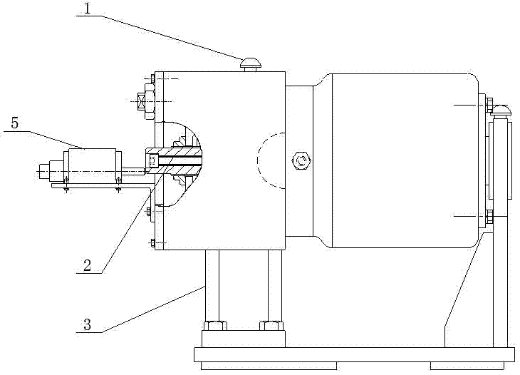
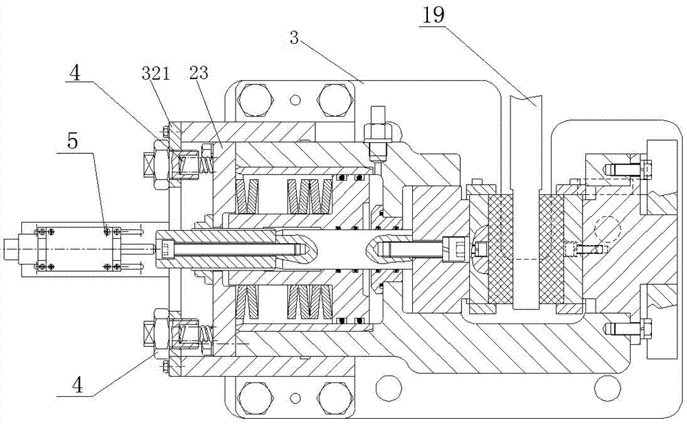
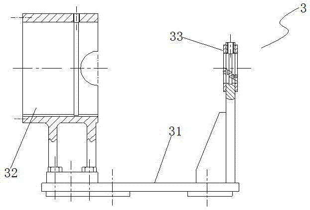
[0042] like Figure 1-10 As shown, a new type of floating disc brake device includes a support 3, a brake housing 7 that is sleeved in the support 3 and can move relative to the support 3 as a whole, and has a gap 9 on the brake housing 7. , The brake housing 7 is provided with a piston chamber 71 and a first guide platen chamber 72 .

[0043] A first through hole 73 is provided between the piston chamber 71 and the first guide platen chamber 72, and the two are connected.

[0044] The inner wall of the piston cylinder 71 is provided with a steel sleeve 14, the steel sleeve 14 is provided with a piston rod 13, and the piston rod 13 is sleeved with a disc spring 15.

[0045] The first guide platen cavity 72 is provided with a first guide platen 11, the first guide platen 11 is connected to the front end of the piston rod 13 through the connecting rod 22 through the first through hole 73, and the front end of the first guide platen 11 is fixed with a first A friction plate 20....


PUM


Abstract

The invention discloses a novel floating type disc shaped braking device. The device comprises a supporting seat and a brake housing, wherein a gap is formed in the brake housing; a piston chamber and a first guide pressing plate chamber which intercommunicate are arranged in the brake housing; a second frictional sheet mounting seat is arranged at one end, far away from the piston chamber, of the brake housing; a gap is formed between the first guide pressing plate chamber and the second frictional sheet mounting seat; a second frictional sheet is fixed to the second frictional sheet mounting seat; a piston rod sleeved with butterfly shaped springs is arranged in the piston chamber; a first guide pressing plate is arranged in the first guide pressing plate chamber; the first guide pressing plate passes through a first through hole through a connecting rod and then is connected to the front end of the piston rod; a first frictional sheet is fixed to the front end of the first guide pressing plate; the piston chamber is a sealing chamber. According to the novel floating type disc shaped braking device, the brake housing is designed to be an integral structure, so that the distance from a rope baffle plate to a brake disc can be reduced; the cost of materials for manufacturing the device can be saved; the cost on infrastructures of a mine can be decreased; in addition, the device is stable and reliable in working.

Description

technical field [0001] The invention belongs to the field of friction speed-regulating braking, and in particular relates to a novel floating disc braking device. Background technique [0002] The disc brake is an indispensable key equipment of the mine hoist, and it is the hydraulic actuator of the brake speed control system of the mine hoist, which plays a vital role in the safe operation of the hoist. [0003] The present mine hoist brake structure is respectively provided with structurally identical oil cylinders and disc spring type disc brakes on both sides of the brake disc. Because there are disc brakes on both sides of the support, the distance between the rope retaining plate and the brake disc on the main shaft device must be increased to lengthen the main shaft and the drum and increase the overall size of the hoist. If it is underground, the chamber space must be increased. The disadvantage it brings is that the lengthening of the main shaft and the drum not o...

Claims


Application Information

Patent Timeline
Patent Type & Authority Applications(China)
IPC IPC(8): B66D5/14B66D5/28F16D65/00
CPCB66D5/14B66D5/28F16D65/005
Inventor 阳芳南李本平李达龚小和李建群
Owner HUNAN YUANYANG COAL MACHINE MFG
Why Eureka
Try Eureka