A control loop of a loader working device

A working device and control circuit technology, which is applied in the field of hydraulic systems, can solve the problems of reduced strength, large space occupation, and easy fatigue of the structure, and achieve the effects of improving operating efficiency, increasing lifting speed, and requiring less space

Active Publication Date: 2017-05-17
TAIYUAN UNIV OF TECH
View PDF12 Cites 0 Cited by
  • Summary
  • Abstract
  • Description
  • Claims
  • Application Information

AI Technical Summary

Problems solved by technology

[0003] In order to utilize this part of the energy, the patent (CN 103225321 A) and the patent (CN 103215978 A) disclose a method, which uses a special mechanical accumulator to recover the energy of the lowering of the arm of the loader. The mechanical accumulator Various devices that can generate elastic potential energy, such as springs and rubber, can be used, but the power density of mechanical accumulators is low, and it takes up a lot of space. It cannot meet the requirements when the weight is large, and the structure is prone to fatigue.
The existing hydraulic gravitational potential energy recovery and reuse system has a complex structure and control of the hydraulic recovery system, and the energy recovery and reuse efficiency is also low
In order to improve this situation, the invention patent (CN 102561442 A) discloses a method that uses one cylinder for energy recovery and direct reuse, which simplifies the structure of the hydraulic system for energy recovery, but needs to add a third independent cylinder
The method disclosed in the invention patent (CN102518606 A) is similar. The principle of energy recovery by three hydraulic cylinders is realized on the excavator through the method disclosed in the patent (CN102660972 A). Large structural changes will affect the mechanical properties of the lifting mechanism, destroy the structural integrity, and reduce the strength

Method used


Image

  • A control loop of a loader working device
  • A control loop of a loader working device
  • A control loop of a loader working device

Examples


Embodiment 1

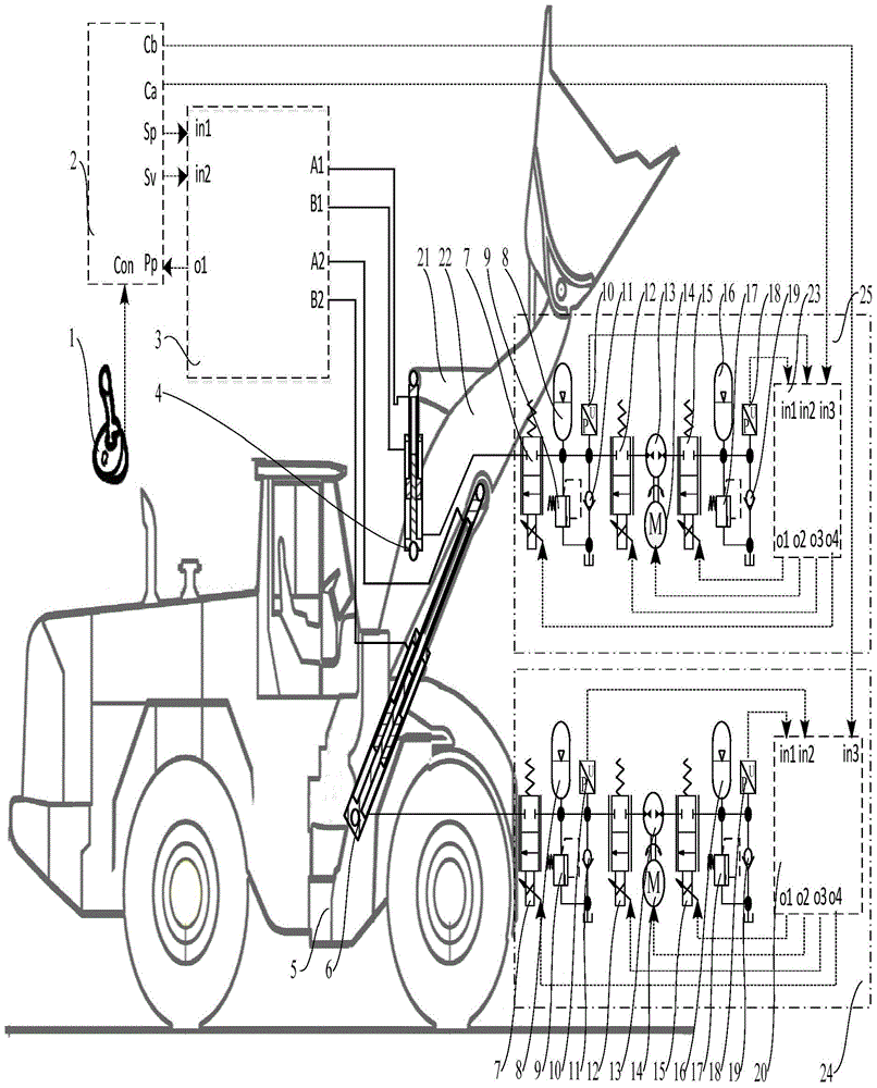
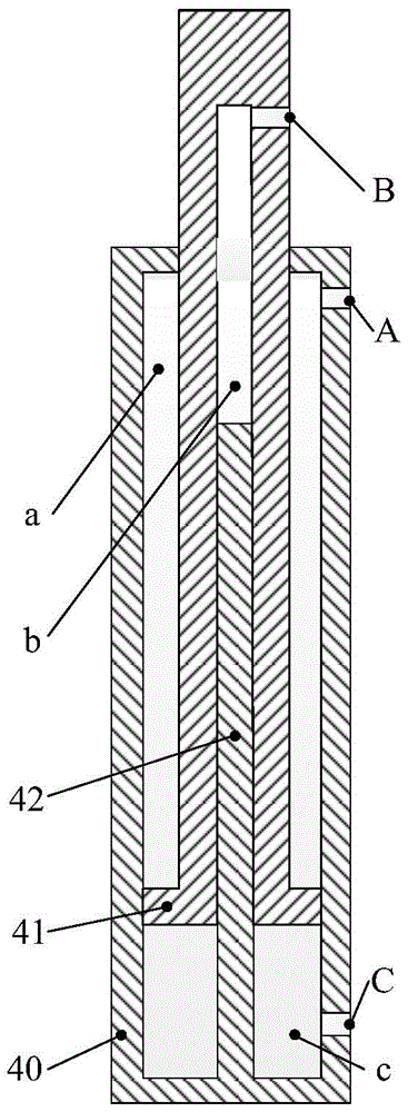
[0034] Embodiment 1: a control loop of a loader working device provided by the present invention, such as figure 1 As shown, it includes: the working mechanism of the loader, the driving circuit 3 of the working device, the control handle 1, and the controller 2, wherein the working mechanism of the loader includes an underframe 5, a boom 22, a bucket and a tipping mechanism 21. The invention also includes: the boom hydraulic cylinder 6 is a hydraulic cylinder with three cavities, the bucket hydraulic cylinder 4 is a hydraulic cylinder with three cavities, the recovery cavity of the boom hydraulic cylinder 6 is connected to the boom recovery hydraulic system 24, The recovery chamber of the dump bucket hydraulic cylinder 4 is connected to the dump bucket recovery hydraulic system 25 . Boom recovery hydraulic system and tipping bucket recovery hydraulic system have the same structure, including: proportional valve 7, balance accumulator 8, balance chamber overflow valve 9, balan...

Embodiment 2

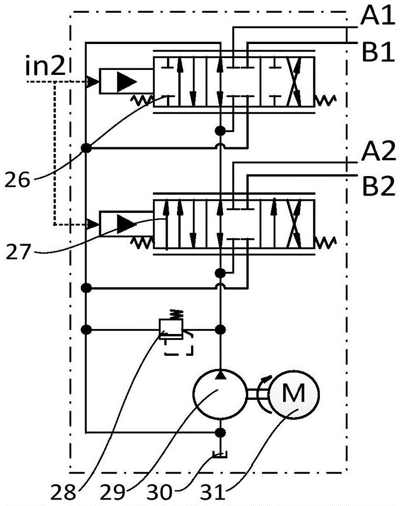
[0047] Embodiment 2: The difference between the structure of this embodiment and Embodiment 1 is that the driving circuit of the work device adopts another open hydraulic circuit, that is, as Figure 4 Closed-center variable pump load-sensing hydraulic system shown.

[0048]The load-sensitive hydraulic system of the neutral closed variable pump includes a bucket control valve 26, a boom control valve 27, an overflow valve 28, a main pump 29, an oil tank 30, a main engine 31, a pressure sensor 32, and a pressure signal controller 33. Wherein, the output shaft of the main engine 31 is connected with the main shaft of the main pump 29, the oil suction port of the main pump 29 is connected with the oil tank 30, the oil outlet of the main pump 29 is connected with the high pressure port of the relief valve 28 and the oil inlet of the boom control valve 27 The oil outlet of the main pump 29 is connected to the inlet of the dump control valve 26 through the neutral channel of the bo...

Embodiment 3

[0049] Embodiment 3: The difference between this embodiment and Embodiment 1 is that the driving circuit of the working device adopts the third open hydraulic circuit, that is, as Figure 5 Inlet and outlet independently controlled hydraulic system shown.

[0050] Import and export independent control hydraulic system includes overflow valve 28, main pump 29, oil tank 30, main engine 31, pressure sensor 32, pressure signal controller 33, dump bucket regeneration control valve 3501, dump bucket hydraulic cylinder extension cavity oil inlet valve 3502 , Oil return valve 3503 for tipping bucket hydraulic cylinder extension cavity, oil inlet valve for tipping bucket hydraulic cylinder retraction cavity 3504, oil return valve for tipping bucket hydraulic cylinder retraction cavity 3505, boom regeneration control valve 3506, boom hydraulic cylinder extension cavity oil inlet Valve 3507, the oil return valve 3508 of the extended chamber of the boom hydraulic cylinder, the oil inlet v...


PUM


Abstract

The invention provides a control loop for a working device of a loader, and belongs to supporting facilities of loaders. The control loop comprises a loader working mechanism, a working device driving loop, a control handle and a controller, wherein the loader working mechanism comprises a bottom frame, a large cantilever, a bucket and a tipping bucket mechanism; a large cantilever hydraulic cylinder is connected between the bottom frame and the large cantilever; a tipping bucket hydraulic cylinder is connected between a tipping bucket arm and the large cantilever. The control loop is characterized in that the large cantilever hydraulic cylinder and the tipping bucket hydraulic cylinder are the hydraulic cylinders provided with three storing chambers, namely, a contracting chamber, an extending chamber and a recovering chamber; the recovering chamber of the large cantilever hydraulic cylinder is connected with a large cantilever recovering hydraulic cylinder; the recovering chamber of the tipping bucket hydraulic cylinder is connected to a recovering hydraulic system; the large cantilever recovering hydraulic system and the recovering hydraulic system are both connected to the controller. According to the control loop for the working device of the loader, a hydraulic control loop rather than an existing mechanical structure of the loader is changed, and thus the working efficiency can be improved.

Description

technical field [0001] The invention relates to a hydraulic system for controlling the working mechanism of a loader, which belongs to the supporting facilities of the loader, in particular to a control circuit for the working device of the loader to reduce its working energy consumption. Background technique [0002] On the loader, the working device driven by the hydraulic cylinder needs to frequently reciprocate up and down. Due to the heavy weight of the working device itself, the hydraulic cylinder needs to overcome the gravity to do work when driving it up. When the working device is lowered, the gravitational potential energy of the working device passes through the hydraulic valve section. The fluid is converted into heat energy and consumed, which not only wastes energy, but also increases the oil temperature and increases the system failure rate. If the gravitational potential energy when the boom is lowered can be recycled, there will be considerable energy saving...

Claims


Application Information

Patent Timeline
Patent Type & Authority Patents(China)
IPC IPC(8): F15B11/08F15B1/02
CPCF15B1/02F15B11/08
Inventor 权龙董致新葛磊黄伟男杨晋
Owner TAIYUAN UNIV OF TECH
Why Eureka
Try Eureka