Efficient heat exchange assembly for refrigeration equipment

A technology for heat exchange components and refrigeration equipment, applied in refrigeration components, refrigerators, refrigeration and liquefaction, etc., can solve the problems of complex structure, difficult maintenance and replacement, easy leakage, etc. leak-prone effect

Inactive Publication Date: 2016-03-30
山东三九制冷设备有限公司
View PDF4 Cites 0 Cited by
  • Summary
  • Abstract
  • Description
  • Claims
  • Application Information

AI Technical Summary

Problems solved by technology

[0003] The heat exchange components used in existing refrigeration devices are mostly sealed or not sealed by manual wrapping. The manual wrapping method will lead to partial wrapping, low efficiency and high cost, and poor wrapping quality will occur. Stability leads to easy leakage of refrigerant liquid, causing commercial complaints; in addition, most of the conduit components are bent from a thicker conduit, which wastes materials and has a small specific surface area, resulting in low cooling efficiency
[0004] Among the relevant patents that have been applied in China, the patent "Efficient Heat Exchange and Heat Exchange Components" (application number: 201220209533.7, publication date: 2012-12-05) discloses a heat exchange device with complex structure but high heat exchange efficiency. However, it does not perform special treatment on joints with complex structures, and there is a problem of easy leakage; the conduit assembly is mounted on the heat conduction sheet, which makes troubleshooting difficult, and maintenance and replacement are not easy at the same time, and the cost of later maintenance and replacement is high
The patent "refrigeration equipment and heat exchanger assembly for refrigeration equipment" (application number: 201510159180.2, publication date: 2015-07-22) discloses a heat exchanger assembly that makes full use of the heat exchange space and uniform heat exchange. However, it achieves the purpose of making full use of the space and exchanging heat evenly by connecting multiple heat exchangers in series. Multiple heat exchangers are arranged at special angles, the structure is too complicated and the scope of application is narrow, and the economy and standardization are poor.

Method used


Image

  • Efficient heat exchange assembly for refrigeration equipment
  • Efficient heat exchange assembly for refrigeration equipment

Examples


Embodiment 1

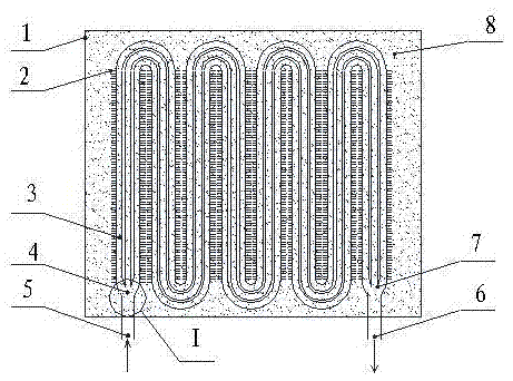
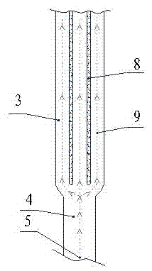
[0017] Such as figure 1 , figure 2 As shown, a high-efficiency heat exchange assembly for refrigeration equipment includes a casing (1) and a conduit assembly (4) arranged in the casing (1), and a gap between the casing (1) and the conduit assembly (4) Filled with copper shavings with a porosity of 60%, the conduit assembly (4) is composed of three pure copper sub-conduits (3) connected in parallel, each sub-conduit (3) is evenly welded with multiple austenite Metal blocks (2) made of stainless steel, the interval between adjacent metal blocks (2) is 20mm, and the two branch conduits (3) are located at the refrigerant liquid inlet (5) and the refrigerant liquid outlet (6). The connection is combined by welding, and the welding joint (7) is sealed with ZP special sealing grease.

[0018] The welding method and the bonding method are all existing technologies in the field of electrical appliances, and will not be described in detail, the same below.

Embodiment 2

[0020] A high-efficiency heat exchange assembly for refrigeration equipment, comprising a shell (1) and a conduit assembly (4) arranged in the shell (1), the gap between the shell 1 and the conduit assembly 4 is filled with a porosity of 60% aluminum chips, the conduit assembly (4) is formed by parallel connection of two pure copper branch conduits (3) ( figure 1 , figure 2 Shown are three sub-conduits (3) connected in parallel), each sub-conduit (3) is uniformly bonded and fixed with a plurality of austenitic stainless steel metal blocks (2), between adjacent metal blocks (2) The distance between the two sub-pipes (3) is combined and communicated at the refrigerant liquid inlet (5) and the refrigerant liquid outlet (6) by welding, and the welded joint (7) adopts ZP special Sealant seal.

Embodiment 3

[0022] A high-efficiency heat exchange assembly for refrigeration equipment, comprising a casing (1) and a conduit assembly (4) arranged in the casing (1), and gaps are filled between the casing (1) and the conduit assembly (4) rate of 40% copper filings, the conduit assembly (4) is formed by parallel connection of five pure copper branch conduits (3) ( figure 1 , figure 2 Shown are three sub-conduits (3) connected in parallel), each sub-conduit (3) is uniformly welded with a plurality of austenitic stainless steel metal blocks (2), and the interval between adjacent metal blocks (2) The five sub-pipes 3 are combined and communicated at the refrigerant liquid inlet (5) and the refrigerant liquid outlet (6) by welding, and the welded joints (7) are sealed with ZP special sealing grease.

[0023] Working principle: the refrigerant flow (9) presses figure 2 The path shown flows in through the refrigerant inlet (5), splits the flow into each sub-conduit (3), conducts heat to th...


PUM


Abstract

The invention discloses an efficient heat exchange assembly for refrigeration equipment. The efficient heat exchange assembly comprises a shell and a guiding pipe assembly, wherein the guiding pipe assembly is arranged in the shell; gaps between the shell and the guiding pipe assembly are filled with high-thermal conductivity solid fillers of which the porosity is 40 to 60 percent; the guiding pipe assembly is formed by connecting at least two pure-copper branch guiding pipes in parallel; the at least two pure-copper branch guiding pipes are merged and communicated with each other at the positions of a refrigeration fluid influx opening and a refrigeration fluid outflux opening through a welding way; welding joints are sealed by adopting ZP special sealing grease. According to the efficient heat exchange assembly disclosed by the invention, the heat exchange area under the same mass is enlarged, the heat exchange area is increased by using a simple way, the economical efficiency is good, and the heat exchange efficiency is high; sealing is carried out by adopting the ZP special sealing grease, so that the adaptability is good, the sealing way is simple, the sealing performance is good, and the problem that leakage can be easily caused due to manual packaging is solved; the structure is simple, a malfunction can be easily eliminated, and maintenance and accessory replacing operation can be easily carried out.

Description

technical field [0001] The invention relates to the refrigeration field, in particular to a high-efficiency heat exchange assembly for refrigeration equipment. Background technique [0002] Heat energy exchange is the most common energy exchange method in both industry and civil use. Tube group heat exchange is the most commonly used heat exchange method in the refrigeration industry and is widely used. [0003] The heat exchange components used in existing refrigeration devices are mostly sealed or not sealed by manual wrapping. The manual wrapping method will lead to partial wrapping, low efficiency and high cost, and poor wrapping quality will occur. Stability leads to easy leakage of refrigerant liquid, causing commercial complaints; in addition, the conduit assembly is mostly bent from a thick conduit, which wastes materials and has a small specific surface area, resulting in low cooling efficiency. [0004] Among the relevant patents that have been applied in China, t...

Claims


Application Information

Patent Timeline
Patent Type & Authority Applications(China)
IPC IPC(8): F25B39/00
CPCF25B39/00
Inventor 任思栋张雁崔腾飞杨振
Owner 山东三九制冷设备有限公司
Why Eureka
Try Eureka