Method for predicting shaking of impeller

A technology of impeller and flutter, which is applied in special data processing applications, instruments, electrical digital data processing, etc., can solve the problems of inability to predict the stability of milling processing, and does not consider the change of workpiece transfer function, etc., to achieve the effect of improving accuracy

Active Publication Date: 2016-03-30
NORTHEASTERN UNIV LIAONING
View PDF2 Cites 3 Cited by
  • Summary
  • Abstract
  • Description
  • Claims
  • Application Information

AI Technical Summary

Problems solved by technology

These scholars also did not consider the continuous change of workpiece transfer function with material removal, and the resulting impact on the accuracy of milling stability prediction
Therefore, the previous prediction method cannot accurately predict the stability of the current milling process in real time during processing.

Method used


Image

  • Method for predicting shaking of impeller
  • Method for predicting shaking of impeller
  • Method for predicting shaking of impeller

Examples


Embodiment Construction

[0039] The specific embodiments of the present invention will be described in detail below in conjunction with the accompanying drawings.

[0040] In this embodiment, the impeller of titanium alloy TC4 is taken as an example. The selected cutting conditions are: the spindle speed is 800rpm, the feed speed is 96mm / min, the cutting depth is 1mm, and the length of the clamping part of the impeller workpiece is 30mm. Choose a ball end milling cutter, semi-contact up milling method, and take 15mm as the axial length of a processing sub-stage in the axial direction of the milling cutter.

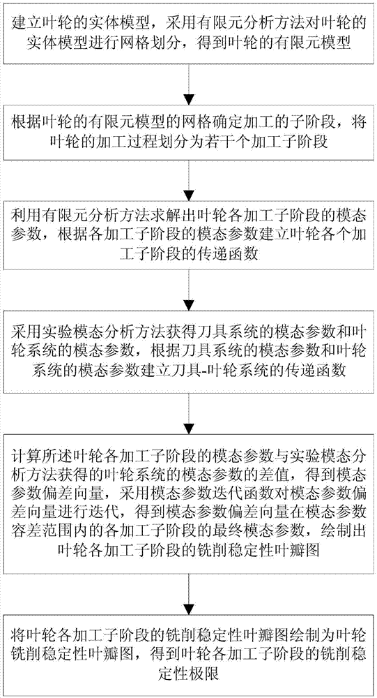
[0041] A method for predicting impeller flutter, such as figure 1 shown, including the following steps:

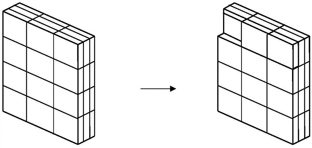
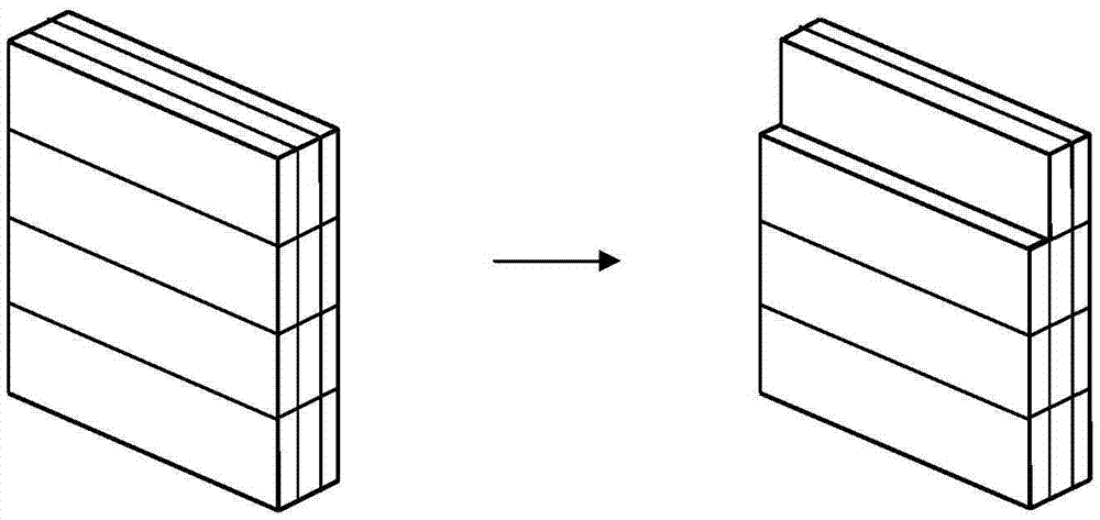
[0042] Step 1: Establish a solid model of the impeller, use the finite element analysis method to mesh the solid model of the impeller, and obtain the finite element model of the impeller.

[0043] In this embodiment, CAD is used for solid modeling of the impeller. Generally, for thin-walle...


PUM


Abstract

The invention provides a method for predicting the shaking of an impeller. The method includes the steps of conducting grid division on an entity model of the impeller through a finite element analysis method, dividing the machining process of the impeller into a plurality of machining sub-stages, obtaining modulus parameters of all the machining sub-stages of the impeller through the finite element analysis method, establishing a transfer function of each machining sub-stage of the impeller, obtaining the modulus parameters of a tool system and the modulus parameters of an impeller system through an experiment modulus analysis method, establishing a transfer function of a tool-impeller system, calculating the difference between the modulus parameters of each machining sub-stage of the impeller and the modulus parameters, obtained through the experiment modulus analysis method, of the impeller system, obtaining the modulus parameter deviation vector, conducting iteration on the modulus parameter deviation vector through a modulus parameter iteration function, obtaining the final modulus parameters of the modulus parameter deviation vector within the modulus parameter tolerance range of all the machining sub-stages, and drawing the milling stability lobe graph of all the machining sub-stages of the impeller.

Description

technical field [0001] The invention belongs to the technical field of impeller machining stability prediction, and in particular relates to a method for predicting impeller flutter. Background technique [0002] Chatter stability prediction method is a very important theoretical method in milling process. It can effectively avoid the deterioration of the machined surface quality caused by regenerative vibration during milling, making it possible to process parts without chatter; thus effectively improving the efficiency and surface quality of milling. [0003] Currently, the use of stability lobe maps is an effective method for predicting milling chatter. The method is based on the system transfer function to establish the relationship between different spindle speeds and the axial depth of cut, and the axial limit depth of cut is used as the stability boundary condition. Since the stiffness of the thin-walled part is similar to that of the cutting tool, its machining dyn...

Claims


Application Information

Patent Timeline
Patent Type & Authority Applications(China)
IPC IPC(8): G06F17/50
CPCG06F30/23G06F2119/18
Inventor 朱立达丁洋刘长福刘宝光金慧成李兆斌史家顺于天彪巩亚东王宛山
Owner NORTHEASTERN UNIV LIAONING
Why Eureka
Try Eureka