A remote fault diagnosis method, device and system for a HVDC converter station

A fault diagnosis, high-voltage direct current technology, applied in image analysis, image enhancement, instruments, etc., can solve the problems of heavy workload, low work efficiency, and large amount of data for operators, and reduce the possibility of subjective judgment errors. Improve work efficiency and reduce workload

Inactive Publication Date: 2018-10-23
CHINA AGRI UNIV
View PDF6 Cites 0 Cited by
  • Summary
  • Abstract
  • Description
  • Claims
  • Application Information

AI Technical Summary

Problems solved by technology

The voltage and current data, fault recording information, and fault traveling wave monitoring data of the converter stations at both ends need to be communicated remotely. The data volume is large, and it is difficult to compare and analyze, which brings a lot of workload to the operating personnel.
[0003] The fault simulation modeling technology is based on typical fault conditions, but sometimes two simultaneous faults, multiple secondary faults caused by a single fault, and atypical faults such as small disturbances may occur in actual engineering. Considering and modeling the actual situation, it is inevitable that the actual fault waveform does not exist in the sample library of typical fault characteristics
[0004] The algorithm used in the existing technology does not take into account the large number of wave recordings of the converter stations at both ends and the huge amount of data of operating parameters such as voltage and current in the actual communication, and the converter stations at both ends directly use all the data for remote communication without screening. Larger, less productive problems

Method used


Image

  • A remote fault diagnosis method, device and system for a HVDC converter station
  • A remote fault diagnosis method, device and system for a HVDC converter station
  • A remote fault diagnosis method, device and system for a HVDC converter station

Examples


Embodiment Construction

[0038] The specific embodiments of the present invention will be described in further detail below with reference to the accompanying drawings and embodiments. The following examples are intended to illustrate the present invention, but not to limit the scope of the present invention.

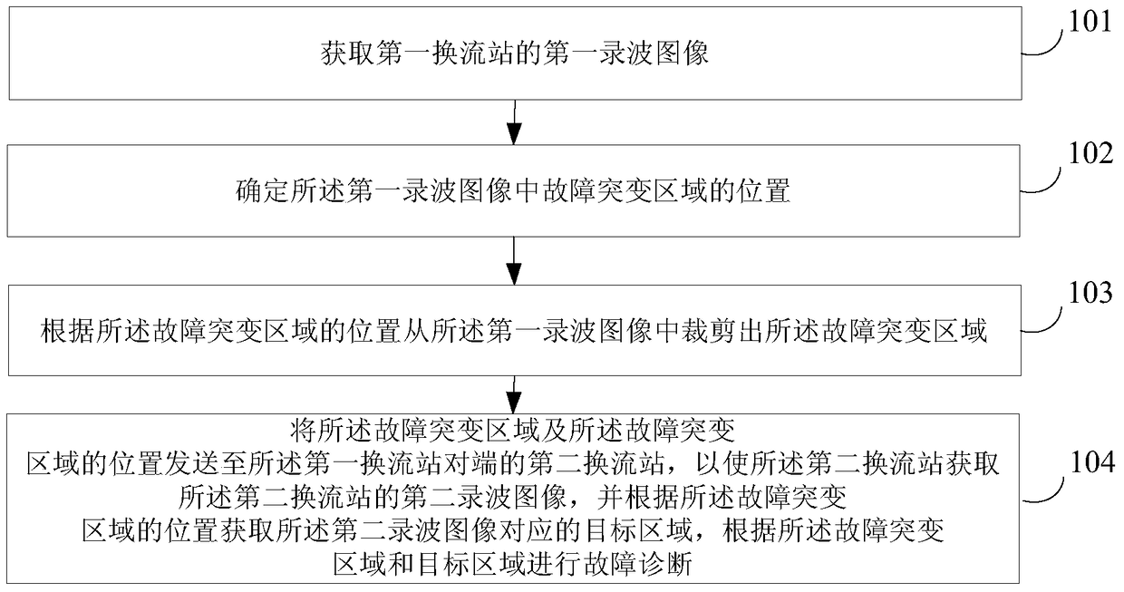
[0039] figure 1 A schematic flowchart of a remote fault diagnosis method for a HVDC converter station provided by an embodiment of the present invention is shown, as shown in figure 1 As shown, the remote fault diagnosis method of the HVDC converter station includes:

[0040] 101. Acquire a first wave-recording image of a first converter station.

[0041] It can be understood that the first converter station refers to the converter station on the site to be diagnosed, and the recorded wave image can be the original measurement data collected, including the voltage, current, and power measurement meters on the site. Current, power value, etc., but not limited to the above examples.

[0042] ...


PUM


Abstract

The invention provides a remote fault diagnosis method, device and system for a high-voltage DC converter station, and relates to the field of fault diagnosis. The method comprises the steps: obtaining a first record image of a first converter station; determining the position of a fault abrupt change area in the first record image; cutting the fault abrupt change area from the first record image according to the position of the fault abrupt change area; enabling the fault abrupt change area and the position of the fault abrupt change area to be transmitted to a second converter station at an opposite end of the first converter station, so as to enable the second converter station to obtain a second record image of the second converter station; obtaining a target region corresponding to the second record image according to the position of the fault abrupt change area; and carrying out the fault diagnosis of the fault abrupt change area and the target region. The method carries out the cutting of the fault abrupt change area in a process of fault diagnosis, so as to reduce the bandwidth occupied for remote transmission, and to reduce the workload of fault diagnosis for a worker.

Description

technical field [0001] The invention relates to the field of fault diagnosis, in particular to a method, device and system for remote fault diagnosis of a high-voltage direct current converter station. Background technique [0002] Most of the existing HVDC transmission systems are DC transmission systems at both ends, including rectifier stations, inverter stations, DC lines, rectifier-side AC systems and inverter-side AC systems. There are many types of faults in HVDC transmission systems, and the sources are also very rich. In the system, the thyristor converter valve, the AC side, the DC line, the DC switch field and the grounding electrode may all fail. Once a fault occurs, the converter stations at both ends need to coordinate and cooperate. The DC lines of long-distance DC transmission systems are generally hundreds to thousands of kilometers. The voltage and current data, fault recording information, fault traveling wave monitoring data, etc. of the converter stat...

Claims


Application Information

Patent Timeline
Patent Type & Authority Patents(China)
IPC IPC(8): G06T7/00G06T7/11
CPCG06T7/0004G06T2207/10004
Inventor 温渤婴杨东冀徐煜敏苗立俐陈泽
Owner CHINA AGRI UNIV
Why Eureka
Try Eureka