High Frequency Resolver

A resolver, high-frequency technology, applied in the direction of transformers, transformer/inductor cores, transformer/inductor components, etc., can solve problems such as reducing the coupling distance of transformers, improve flatness and consistency, and improve efficiency , the effect of improving the coupling efficiency

Active Publication Date: 2017-12-26
SUZHOU INST OF BIOMEDICAL ENG & TECH CHINESE ACADEMY OF SCI
View PDF3 Cites 0 Cited by
  • Summary
  • Abstract
  • Description
  • Claims
  • Application Information

AI Technical Summary

Problems solved by technology

[0003] Aiming at the deficiencies in the above-mentioned technologies, the present invention provides a high-frequency rotary transformer in which a first printed circuit board drawing coil is wound around a second magnetic core provided with a second printed circuit board drawing coil. The rotation of the central axis of the magnetic core realizes electromagnetic coupling to form a rotary transformer, without the need to manually wind the transmission coil, which solves the consistency problem of the manual winding transmission coil, which not only improves the efficiency of transformer processing and production, but also helps reduce the coupling distance of the transformer so that Facilitates the coil installation of transformers with small structures

Method used


Image

  • High Frequency Resolver
  • High Frequency Resolver
  • High Frequency Resolver

Examples


Embodiment 1

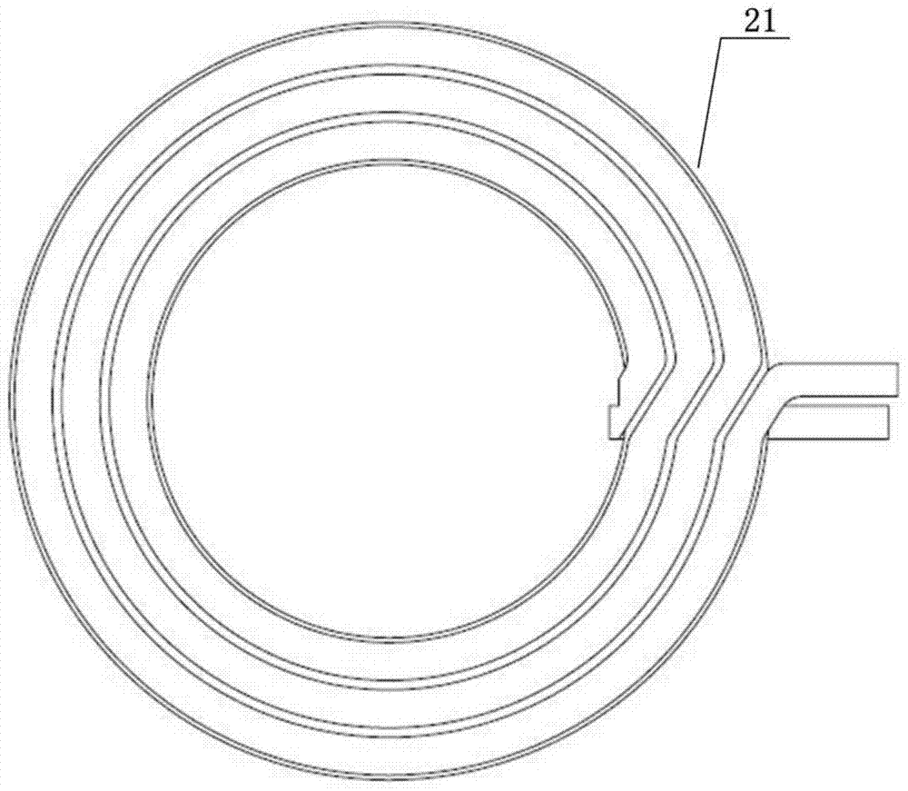
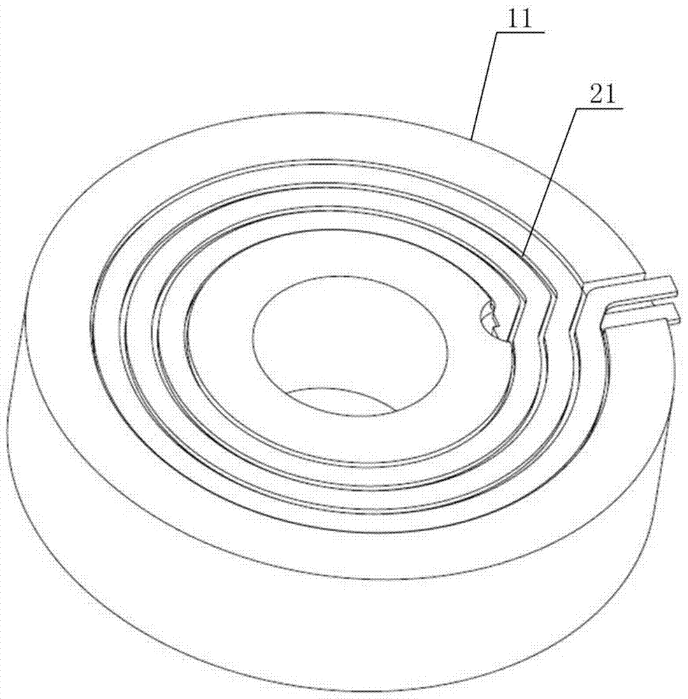
[0049] On the basis of the embodiments of the present invention, this embodiment provides a specific embodiment of a high-frequency rotary transformer, such as Figure 1 to Figure 5 shown.

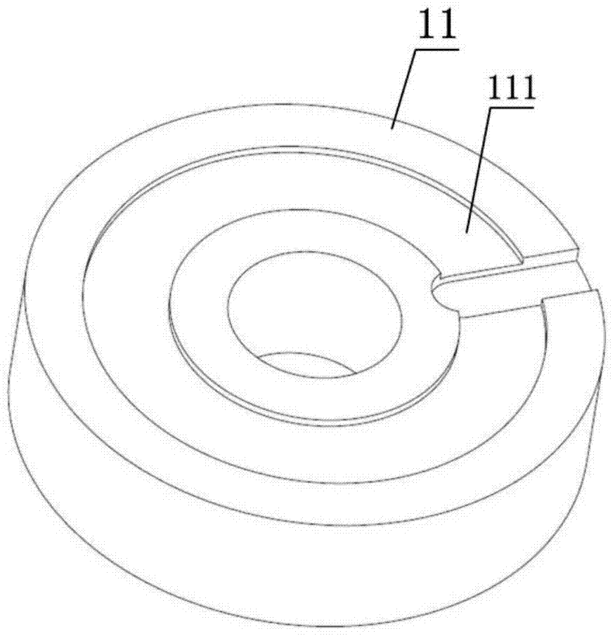
[0050] Such as figure 1 As shown, the first printed circuit board drawing coil 21 and the second printed circuit board drawing coil 22 are planar. Such as figure 2 with image 3 As shown, the first magnetic core 11 and the second magnetic core 12 are both hollow columns, and the fixed shaft (not shown in the figure) of the first magnetic core 11 is fixedly installed in the hollow structure of the first magnetic core 11, and the fixed shaft The second magnetic core 12 is slidably connected to the second magnetic core 12 through the bearing, and the second magnetic core 12 rotates around the fixed axis of the first magnetic core 11 through the bearing, that is, the second magnetic core 12 rotates around the central axis of the first magnetic core 11 . The first magnetic core 11 is provi...

Embodiment 2

[0056] On the basis of the embodiments of the present invention, this embodiment provides a specific embodiment of a high-frequency rotary transformer, such as Figure 6 to Figure 8 shown.

[0057] Such as Image 6 with Figure 7 As shown, the first printed circuit board drawing coil 21 and the second printed circuit board drawing coil 22 are all crimped in a hollow cylindrical shape; Figure 8 As shown, the first magnetic core 11 is in the shape of a cylinder, the first printed circuit board drawing coil 21 is sleeved on the outside of the first magnetic core 11 in parallel with the radial direction of the first magnetic core 11, and the second magnetic core 12 is provided with a housing The cylindrical groove of the first magnetic core 11 , the second printed circuit board draws the coil 22 on the surface of the cylindrical groove, and the second magnetic core 12 rotates around the central axis of the first magnetic core 11 .

[0058] In this embodiment, the embedded inst...


PUM


Abstract

The invention discloses a high-frequency rotary transformer, comprising: a magnetic core, which includes a first magnetic core and a second magnetic core; a printed circuit board drawing coil, which includes a first printed circuit board drawing coil and a second printed circuit Board drawing coil; the first printed circuit board drawing coil is arranged on the first magnetic core, and the second printed circuit board drawing coil is arranged on the second magnetic core and the first printed circuit board drawing coil The circuit board draws the relative positions of the coils; wherein, the second magnetic core rotates around the central axis of the first magnetic core to realize electromagnetic coupling. The invention does not need to manually wind the transmission coil, solves the consistency problem of the manual winding transmission coil, improves the controllable precision of the distance between the first magnetic core and the second magnetic core of the rotary transformer, reduces the size of the transformer, and improves the magnetic field of the transformer. Coupling effectiveness.

Description

technical field [0001] The present invention relates to the technical field of high-frequency signal transmission, and more specifically, the present invention relates to a high-frequency rotary transformer. Background technique [0002] In electromechanical systems, it is often encountered that a signal or energy needs to be transmitted from one end of relative rotation to the other. Generally, brushes with spring contacts are sufficient for energy or signal transmission. However, when the transmission frequency is high or the speed is fast, the contact transmission method will cause instability caused by wear, and the friction of the contacts will also introduce certain system noise. In addition, the transmission coil of the ordinary magnetic core resolver is wound into a spring shape and installed on the coupling magnetic core to realize the signal transmission function. However, due to the installation accuracy of this magnetic core, the magnetic core rotor and stator ...

Claims


Application Information

Patent Timeline
Patent Type & Authority Patents(China)
IPC IPC(8): H01F38/18H01F27/28H01F27/30H01F27/24
CPCH01F27/24H01F27/2804H01F27/2895H01F27/306H01F38/18H01F2027/2819
Inventor 韩志乐向永嘉崔崤峣简小华邵维维
Owner SUZHOU INST OF BIOMEDICAL ENG & TECH CHINESE ACADEMY OF SCI
Why Eureka
Try Eureka