Electrochemical energy storage device
What is Al technical title?
Al technical title is built by PatSnap Al team. It summarizes the technical point description of the patent document.
An energy storage device and electrochemical technology, applied in the field of electrochemistry, can solve the problems of viscous cells entering the shell, etc., and achieve the effect of fixed connection
Active Publication Date: 2016-03-30
DONGGUAN AMPEREX TECH +1
View PDF5 Cites 15 Cited by
Summary
Abstract
Description
Claims
Application Information
AI Technical Summary
This helps you quickly interpret patents by identifying the three key elements:
Problems solved by technology
Method used
Benefits of technology
Problems solved by technology
[0004] In view of the problems existing in the background technology, the object of the present invention is to provide an electrochemical energy storage device, which can not only realize the fixed connection between the battery cell and the packaging case, but also solve the problems that occur during the drop test. Various problems, and can avoid the problem that the battery core is difficult to enter the shell caused by the stickiness on both sides of the adhesive material
Method used
Image
Click on the blue label to locate the original text in one second.
Reading with bidirectional positioning of images and text.
Examples
Embodiment 1
[0054] 1. Preparation of positive electrode sheet
[0055] LiCoO 2 , conductive carbon, and polyvinylidene fluoride are dispersed in N-methylpyrrolidone at a weight ratio of 96:1:3 to make a positive electrode slurry, which is then coated and compacted into a positive electrode sheet with a thickness of 100 μm.
[0056] 2. Preparation of negative electrode sheet
[0057] Disperse graphite, conductive carbon, sodium carboxymethyl cellulose, and styrene-butadiene rubber in deionized water at a weight ratio of 97:1:1:1 to make negative electrode slurry, and then coat and compact to make a negative electrode with a thickness of 90 μm piece.
[0058] 3. Electrolyte Preparation
[0059] Prepare EC, PC, DEC, and EMC in a weight ratio of 20:20:50:10 to make a non-aqueous organic solvent, add 1mol / L LiPF 6 As a lithium salt, the preparation of the electrolyte is completed.
[0060] 4. Cell preparation
[0061] The prepared positive electrode sheet, PP separator, and negative elec...
Embodiment 2
[0070] Lithium-ion secondary batteries were prepared according to the method of Example 1, except for the following differences:
[0071] 5. Preparation of Adhesives
[0072] The thickness of the second functional layer was 20 μm.
Embodiment 3
[0074] Lithium-ion secondary batteries were prepared according to the method of Example 1, except for the following differences:
[0075] 5. Preparation of Adhesives
[0076] The thickness of the second functional layer was 40 μm.
PUM
Property
Measurement
Unit
thickness
aaaaa
aaaaa
thickness
aaaaa
aaaaa
thickness
aaaaa
aaaaa
Abstract
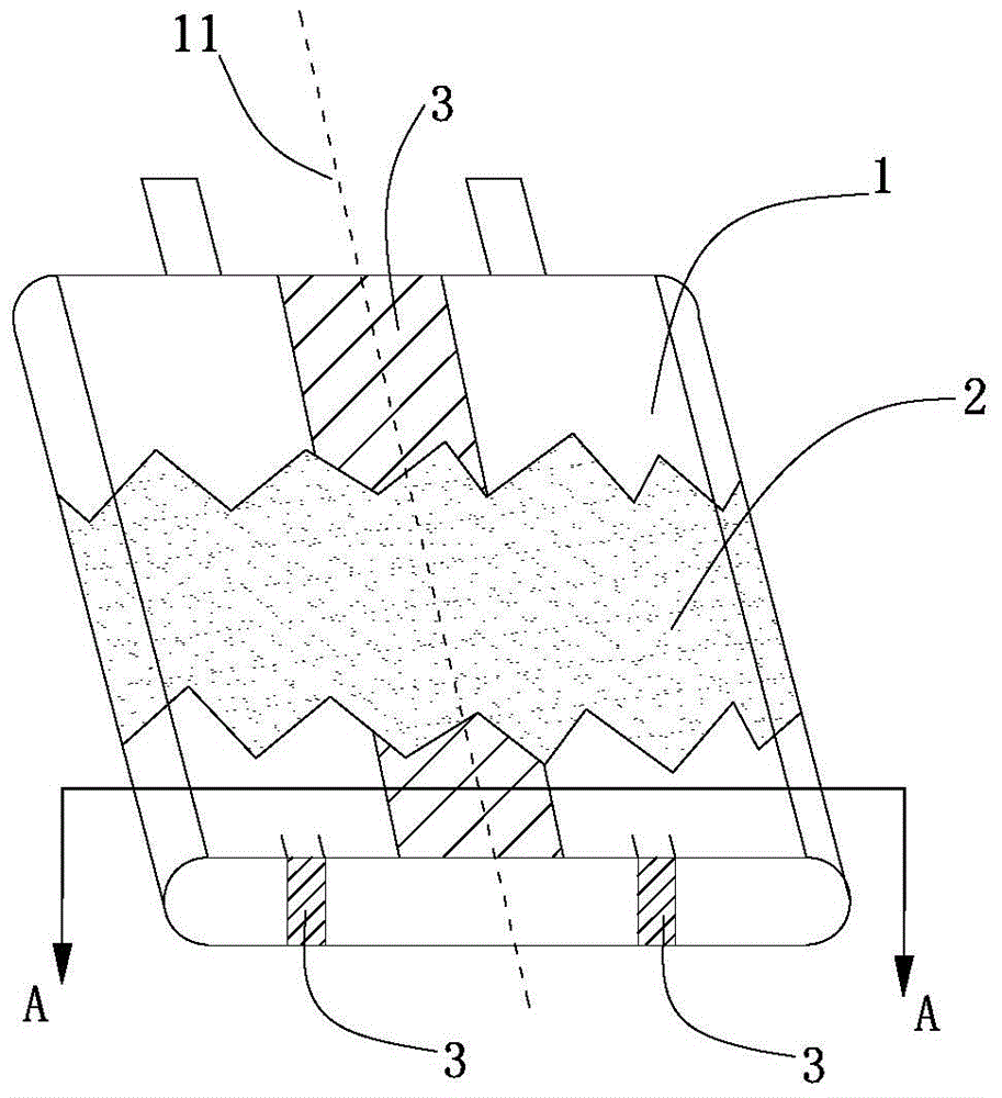
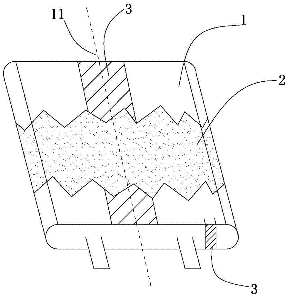
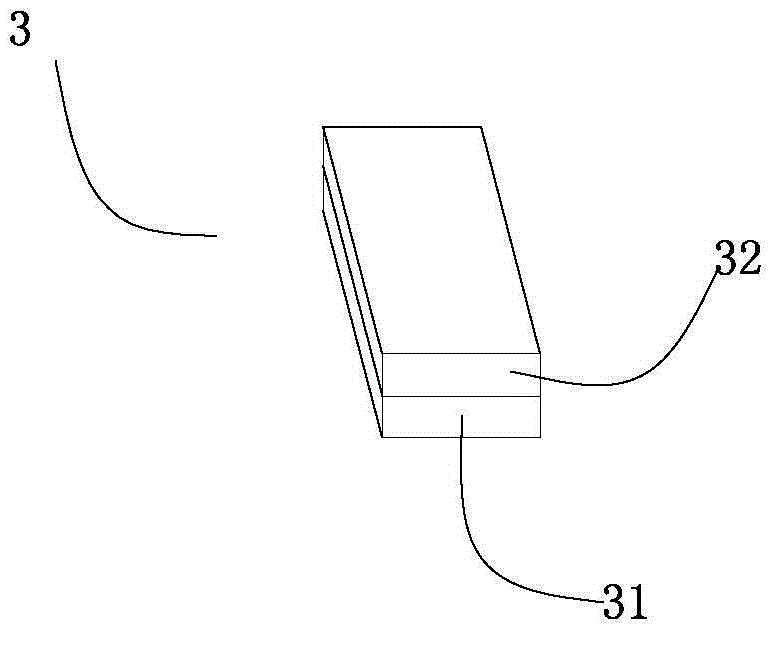
The present invention provides an electrochemical energy storage device. The electrochemical energy storage device comprises an electrical core (1), an electrolyte and a packaging casing (2). The electrochemical energy storage device further comprises a glue material (3) located between the electrical core (1) and the packaging casing (2). The glue material (3) comprises a first adhesive layer (31) and a second functional layer (32). The first adhesive layer (31) is bonded directly or indirectly on the outer surface of the electrical core (1); the second functional layer (32) is arranged on one side opposite to the surface, of the electrical core (1), on which the first adhesive layer (31) is bonded directly or indirectly, before a pressure is applied to the electrochemical energy storage device, the electrical core (1) is not bonded with the packaging casing (2), and after the pressure is applied to the electrochemical energy storage device, the electrical core (1) is bonded with the packaging casing (2). The electrochemical energy storage device can achieve fixed connection between the electrical core and the packaging casing, solves the problems of a drop testing process, and can also solve the problem that packaging of the electrical core into the casing is difficult due to viscidity of both sides of the glue material.
Description
technical field [0001] The invention relates to the field of electrochemical technology, in particular to an electrochemical energy storage device. Background technique [0002] Due to the advantages of high voltage, small size, light weight, high specific capacity, no memory effect, no pollution, small self-discharge and long cycle life, lithium-ion secondary batteries make them widely used in communications, electrical appliances, electronic information, power equipment and The application of energy storage and other fields has achieved unprecedented development, and with the rapid development of society, people put forward higher requirements for the energy density, charge and discharge speed, cycle life and safety performance of lithium-ion secondary batteries. [0003] The drop test is a more stringent safety test for lithium-ion secondary batteries. Lithium-ion secondary batteries are extremely prone to problems such as top seal breaking, liquid leakage, separator wri...
Claims
Application Information
Patent Timeline
Application Date:The date an application was filed.
Publication Date:The date a patent or application was officially published.
First Publication Date:The earliest publication date of a patent with the same application number.
Issue Date:Publication date of the patent grant document.
PCT Entry Date:The Entry date of PCT National Phase.
Estimated Expiry Date:The statutory expiry date of a patent right according to the Patent Law, and it is the longest term of protection that the patent right can achieve without the termination of the patent right due to other reasons(Term extension factor has been taken into account ).
Invalid Date:Actual expiry date is based on effective date or publication date of legal transaction data of invalid patent.