Driving method and circuit for permanent magnet synchronous motor

A technology of permanent magnet synchronous motor and driving method, which is applied in the direction of electronic commutator, current controller, etc., can solve the problems that cannot eliminate the accumulation error of engraving line, the drift phenomenon of motor stability, and affect the stability of motor speed, etc., to achieve The effect of improving control stability, eliminating high-order harmonic pulsation, and improving speed stability

Inactive Publication Date: 2016-03-30
XIAN ZHONGKE PHOTOELECTRIC PRECISION ENG CO LTD
View PDF4 Cites 1 Cited by
  • Summary
  • Abstract
  • Description
  • Claims
  • Application Information

AI Technical Summary

Problems solved by technology

[0004] 1) The existing sine wave permanent magnet synchronous motor adopts PWM drive control technology. Due to the high switching frequency of PWM control, the current of the motor produces high-order harmonic changes other than the fundamental wave, thereby causing torque ripple of the motor rotor Phenomenon, directly affect the motor speed stability;
[0005] 2) The existing self-controlled sine wave permanent magnet synchronous motor is mainly designed for the automatic control system. The encoder used in it has only one zero pulse at a mechanical angle of 360°, which cannot eliminate the accu

Method used


Image

  • Driving method and circuit for permanent magnet synchronous motor
  • Driving method and circuit for permanent magnet synchronous motor
  • Driving method and circuit for permanent magnet synchronous motor

Examples


Example Embodiment

[0031] The present invention will be described in detail below with reference to the accompanying drawings and specific embodiments.

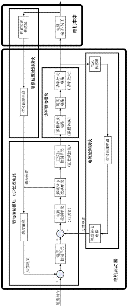
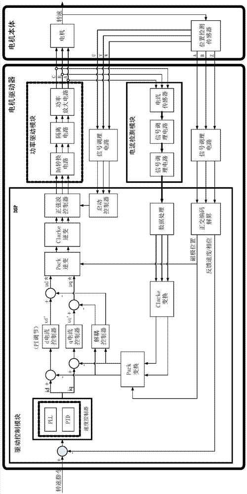
[0032] The permanent magnet synchronous motor drive circuit of the present invention adopts three-phase analog sine wave drive technology, and adopts the permanent magnet synchronous motor driver with multi-zero encoder feedback and PLL constant speed control. It is composed of four parts: drive control module, current detection module, power drive module and magnetic pole position detection module. figure 1 .

[0033] The drive control module includes a speed calculation unit, a speed control unit, a current control unit, a decoupling change unit and a sine wave control unit; the current detection module is mainly composed of a current detection circuit, a signal conditioning circuit and an analog-to-digital conversion circuit; the power drive module It is composed of a digital-to-analog conversion circuit, an isolation circuit and a power am...


PUM


Abstract

The invention provides a driving method and circuit for a permanent magnet synchronous motor. The driving circuit for the permanent magnet synchronous motor comprises a driving control module, a current detection module, a power driving module and a magnetic pole position detection module; the driving control module comprises a speed solving unit, a speed control unit, a current control unit, a decoupling variation unit and a sine wave control unit; the current detection module comprises a current detection circuit, a signal conditioning circuit and an analog-digital conversion circuit; the magnetic pole position detection module comprises a magnetic pole position detection sensor and a signal conditioning circuit; through PLL/PID dual-mode control, the problem that the traditional PID controlled motor has the phenomenon of control delay due to time draft in stability can be solved and the stability of the speed of the motor can be improved further.

Description

【Technical field】 [0001] The invention belongs to the technical field of automatic motor control, and relates to a driving method and circuit of a permanent magnet synchronous motor. 【Background technique】 [0002] In the indoor space measurement and positioning system, the sine wave permanent magnet synchronous motor is used to drive the optical electromechanical rotor to provide time difference measurement, and the motor speed stability is the key technical index of the system. [0003] The existing sine wave permanent magnet synchronous motor has the following problems: [0004] 1) The existing sine wave permanent magnet synchronous motor adopts PWM drive control technology. Because PWM control has a high switching frequency, the current of the motor produces higher harmonic changes other than the fundamental wave, thereby causing torque pulsation of the motor rotor. phenomenon, which directly affects the stability of the motor speed; [0005] 2) The existing self-contr...

Claims


Application Information

Patent Timeline
IPC IPC(8): H02P6/17H02P6/28
Inventor 梁选森吴易明赵晓进林俤靳亚丽
Owner XIAN ZHONGKE PHOTOELECTRIC PRECISION ENG CO LTD
Why Eureka
Try Eureka