Water-cooled radiator, fabrication method thereof and cooling device with radiator

A manufacturing method and radiator technology, applied in the direction of cooling/ventilation/heating transformation, etc., can solve the problems of assembly accuracy relying on manual operation, complex shape, and reduced production capacity, and achieve continuity and stability of heat conduction performance, internal corrosion resistance Improvement, heat dissipation surface area optimization effect

Active Publication Date: 2016-03-30
HUIZHOU TAIDING ELECTRONICS TECH CO LTD
View PDF5 Cites 10 Cited by
  • Summary
  • Abstract
  • Description
  • Claims
  • Application Information

AI Technical Summary

Problems solved by technology

Before entering the furnace for welding, it is necessary to use various fixtures to assemble and fix the corrugated sheets, pipes, water chambers and other parts. The shape of the joint between the flat pipe and the water chambers at both ends is complicated and there are many dead angles. During welding, there are often missing welds and false welds. The welding part cannot be effectively detected in the production line. After being installed, it has experienced multiple thermal shocks and the resulting thermal expansion and contraction effects, as well as liquid leakage from the virtual soldering part under vibration conditions. It has been a persistent quality problem that has plagued the water cooling industry for many years.
Leakage and lack of water will cause the lack of working fluid and stop the circulation, which will not be able to effectively take away the heat of the water-cooled head, causing damage to components at the slightest, and system crashes and data loss at worst

Method used


Image

  • Water-cooled radiator, fabrication method thereof and cooling device with radiator
  • Water-cooled radiator, fabrication method thereof and cooling device with radiator
  • Water-cooled radiator, fabrication method thereof and cooling device with radiator

Examples


Embodiment 1

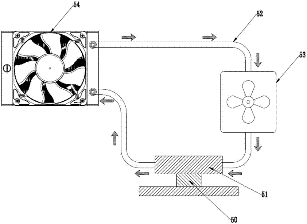
[0041] See water cooling systems such as figure 1 , including: heat source (Heatsource) 50, water cooling head 51 (collector Waterblock), circulation pipe 52 (pipe), water pump 53 (Pump), working liquid water, air-cooled radiator 54 (Radiator).

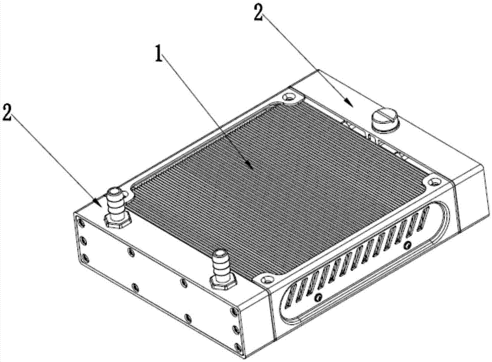
[0042] The radiator provided by this embodiment is as figure 2 , image 3 , Figure 4 ,include:

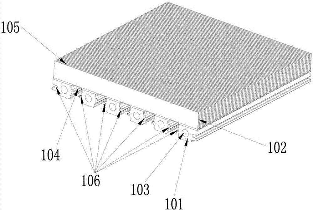
[0043] Heat sink 1, the heat sink 1 includes a metal body 101 with a plurality of grooves and a plurality of heat dissipation fins 102 above the metal body 101, the metal body 101 is provided with water cooling channels 103 running through its two ends, the metal body The gap between the groove of 101 and the heat dissipation fins 102 is directly connected to form a first heat dissipation air channel 104, and a second heat dissipation air channel 105 is separated between two adjacent heat dissipation fins 102. A heat dissipation air duct 104 and a second heat dissipation air duct 105 communicate with each other, and the bottom ends o...

Embodiment 2

[0061] Figure 10 , Figure 11 as well as Figure 12 A second embodiment of the present invention is illustrated. This example and Figure 2~4 The difference of the first embodiment shown in is that the water tank is made of metal, and the bottom end cover 203 and the top end cover 205 of the water chamber and the second sealing gasket 204 are combined by riveting process, so that the water chamber forms a water chamber sealed from the outside world The cavity 201, and the partition wall that controls the flow direction of water in the cooling body and the partition series and parallel combination also adopts the metal partition sheet 208. The purpose of using a metal water tank is to adapt to the application environment with different temperature and mechanical strength requirements, and its basic structure and principle are the same.

[0062] The water tank 2 includes a first sealing gasket 202 , a water chamber bottom end cover 203 , a second sealing gasket 204 and a wa...

Embodiment 3

[0064] Figure 13 and Figure 14 The third embodiment of the present invention is illustrated in conjunction with the schematic diagram of the manufacturing process. This example and Figure 2~4 The difference of the first embodiment shown in is that the heat dissipation area of ​​the heat sink is further expanded, and the heat sink 1 includes a metal body 101 with more than one groove, and a plurality of heat dissipation fins 102 arranged above the body, in order to further expand The heat dissipation area is also provided with heat dissipation fins 102 below the metal body 101, and the bottoms of the upper and lower heat dissipation fins 102 are naturally connected to the metal body 101 as an overall structure; the metal body 101 on both sides of the groove is provided with The water-cooling channels 103 formed by the circular or special-shaped holes running through both ends can be used for liquid circulation, and the metal body 101 with through holes and the liquid insid...


PUM


Abstract

The invention discloses a water-cooled radiator, a fabrication method thereof and a cooling device with the radiator. The water-cooled radiator comprises a heat sink and water tanks, wherein the heat sink comprises a groove-shaped metal body and a plurality of cooling fins, the cooling fins are arranged on the body, the metal body is provided with a plurality of water-cooled passages passing through the two ends of the metal body, gaps between grooves and the cooling fins are directly communicated in a pass-through way to form first cooling air ducts in a penetrating way, a second cooling air duct is formed between adjacent two cooling fins, the first cooling air duct and the second cooling air duct are mutually communicated, the bottoms of the cooling fins and the metal body are a continuous integrated structure, the water tanks are arranged at the two opposite ends of the metal body and are provided with water chambers used for accommodating a working liquid, and the water-cooled passages are communicated with the water chambers. The fins and the metal body are the integrated structure, the problems of influence in heat conduction and liquid leakage caused by unfavorable welding are prevented to the greatest extent, the welding process is substituted by integrated molding, the first yield is high, the manufacturing cost is relatively reduced, the cooling efficiency is high in stability, and high consistency is achieved.

Description

technical field [0001] The invention relates to a water-cooled radiator, a manufacturing method thereof, and a radiator with the radiator. Background technique [0002] The radiator is used to speed up the heat dissipation, which can transfer the heat of the heating element to the air and prolong the service life of the heating object. For example, the current electronics industry is developing rapidly, and many electronic devices will involve heat dissipation issues. To dissipate heat from electronic devices, radiators must be used. [0003] The general radiator adopts the structure of heat sink and heat dissipation fan, and it can also achieve better heat dissipation effect by designing a reasonable internal and external structure. However, some electronic systems with high heating power or relatively concentrated heating power density often cannot accommodate a large air-cooled radiator above the heat source or cannot meet the required heat dissipation performance due to...

Claims


Application Information

Patent Timeline
Patent Type & Authority Applications(China)
IPC IPC(8): H05K7/20B23P15/26
Inventor 段强飞
Owner HUIZHOU TAIDING ELECTRONICS TECH CO LTD
Why Eureka
Try Eureka