Exhaust gas treatment method, and exhaust gas treatment device

A technology for waste gas treatment and waste gas, which is applied in the direction of gas treatment, separation methods, chemical instruments and methods, etc., can solve problems such as difficulty in use, and achieve the effects of reducing water vapor, easy maintenance, and simplifying waste gas treatment devices

Active Publication Date: 2016-03-30
OSAKA PREFECTURE UNIV PUBLIC CORP +1
View PDF13 Cites 1 Cited by
  • Summary
  • Abstract
  • Description
  • Claims
  • Application Information

AI Technical Summary

Problems solved by technology

In addition, since the combustion exhaust gas contains SO from glass raw materials x , Adhesive components and other catalyst

Method used


Image

  • Exhaust gas treatment method, and exhaust gas treatment device
  • Exhaust gas treatment method, and exhaust gas treatment device
  • Exhaust gas treatment method, and exhaust gas treatment device

Examples


Embodiment Construction

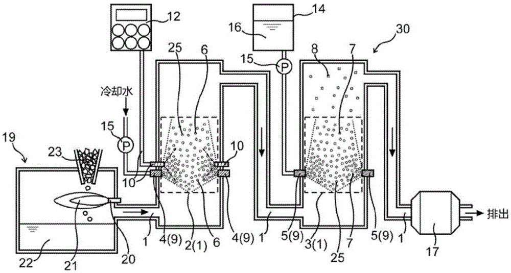
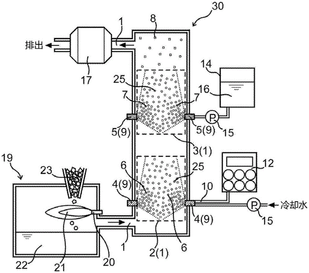
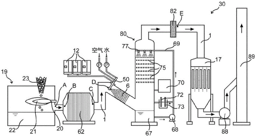
[0036] The exhaust gas treatment method of the present invention is characterized in that the method includes the following steps: x Water or an aqueous solution and ozone as the first liquid are supplied to the waste gas at a temperature above 150° C. to generate a first mist in which water droplets of the first liquid float in the waste gas containing ozone gas.

[0037] In the present invention, mist refers to a gas in which many water droplets float. Therefore, the mist includes a plurality of water droplets floating (liquid phase) and a gas (gas phase) around the water droplets.

[0038] In the exhaust gas treatment method of the present invention, preferably, the first mist is generated by spraying the first liquid in the exhaust gas, and ozone gas is supplied to the generated first mist.

[0039] According to such a structure, the 1st mist in which the water droplet of the 1st liquid floats can be generated in the exhaust gas containing ozone gas. In addition, when th...


PUM


Abstract

This exhaust gas treatment method is characterized by involving a step for supplying ozone and a first liquid, which is water or an aqueous solution, into an exhaust gas that contains NOx and that is 150 DEG C or higher, and for generating a first mist, in which the water droplets of the first liquid are suspended, in the exhaust gas containing ozone gas. This exhaust gas treatment method may also involve a step for generating, in the exhaust gas that passed through the first mist, a second mist by spraying a second liquid which is a reducing agent aqueous solution.

Description

technical field [0001] The invention relates to a waste gas treatment method and a waste gas treatment device. Background technique [0002] Glass products such as glass bottles are produced by melting raw materials such as quartz sand, soda ash, lime, etc., and cullet obtained by crushing empty bottles, etc., with a burner in a furnace (about 1500°C), and molding the molten glass. The combustion exhaust gas containing the combustion exhaust gas from the burner and the components derived from the molten glass is discharged from the melting furnace in which the glass is melted. The combustion exhaust gas discharged from the furnace contains air pollutant NO x or SO x , these pollutants need to be removed from the combustion exhaust before it is released into the atmosphere. In addition, since the combustion exhaust gas contains SO from glass raw materials x , Adhesive components and other catalyst poisoning components, therefore, it is difficult to use the conventional NO...

Claims


Application Information

Patent Timeline
IPC IPC(8): B01D53/56B01D53/18B01D53/50B01D53/77
CPCB01D53/60B01D53/79B01D2251/104B01D2251/304B01D2251/306B01D2258/0283Y02A50/20
Inventor 黑木智之大久保雅章藤岛英胜山本柱鸟居丰彦藤本直行
Owner OSAKA PREFECTURE UNIV PUBLIC CORP
Why Eureka
Try Eureka