Pneumatic control cutting-off machine

A pneumatic control and cutting machine technology, applied in the direction of shearing devices, manufacturing tools, shearing equipment, etc., can solve the problem of cutting debris flying and hurting the operator or other personnel, the quality of the cut material is unstable, the cutting surface is not smooth, etc. problems, to avoid quality problems, simple structure, and stable operation

Active Publication Date: 2016-04-06
CHUZHOU JINGYI MOLD EQUIP MFG
View PDF5 Cites 0 Cited by
  • Summary
  • Abstract
  • Description
  • Claims
  • Application Information

AI Technical Summary

Problems solved by technology

At present, the cutting of metal materials is generally carried out by manual cutting machines. Some irregular materials are difficult to clamp and process. Moreover, through manual operation, not only the work efficiency is slow, but the quality of the cut materials is unstable, and the cutting surface is often not smooth. In case of inclination, etc., the subsequent use of metal materials should be
Moreover, through manual mechanical cutting, it is also possible that during the cutting process, the cutting debris will fly and injure the operator or other personnel.

Method used


Image

  • Pneumatic control cutting-off machine
  • Pneumatic control cutting-off machine

Examples


Embodiment Construction

[0012] The following will clearly and completely describe the technical solutions in the embodiments of the present invention with reference to the accompanying drawings in the embodiments of the present invention. Obviously, the described embodiments are only some, not all, embodiments of the present invention. Based on the embodiments of the present invention, all other embodiments obtained by persons of ordinary skill in the art without making creative efforts belong to the protection scope of the present invention.

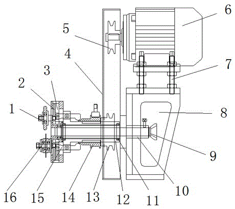
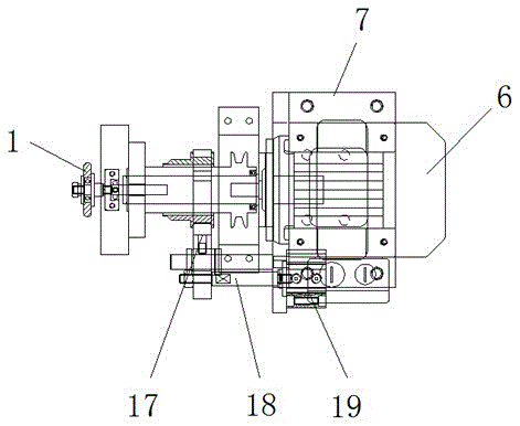
[0013] see Figure 1-2 , the present invention provides a technical solution: a pneumatic control cutting machine, including a three-phase asynchronous motor 6, the output end of the three-phase asynchronous motor 6 is fixedly installed with a first pulley 5, the three-phase asynchronous motor 6 The lower part is fixedly connected with the base 8 through the screw 7, and the shaft 10 is fixedly installed in the inner cavity on the left side of the base 8, and ...


PUM


Abstract

The invention discloses a pneumatic control cutting-off machine. The pneumatic control cutting-off machine comprises a three-phase asynchronous motor. A first belt wheel is fixedly installed at the output end of the three-phase asynchronous motor. The lower portion of the three-phase asynchronous motor is fixedly connected with a base through a screw. A shaft is fixedly installed in an inner cavity in the left side of the base. A core bar is movably installed in an inner cavity of the shaft. A rotating shaft is movably arranged on the outer side of the middle of the core bar through a rolling bearing. A second belt wheel is fixedly arranged on the outer side of the rotating shaft. A sliding sleeve is movably installed on the left side of the second belt wheel. A rocker is fixedly arranged at the left end of the rotating shaft. The left end of the rocker is movably connected with a sliding block. A fixed block is fixedly arranged on the left side of the sliding block. The pneumatic control cutting-off machine is simple in structure, convenient to use, practical and capable of achieving automatic cutting, manual operation is not needed any more, and work efficiency is greatly improved.

Description

technical field [0001] The invention relates to the technical field of cutting machines, in particular to a pneumatically controlled cutting machine. Background technique [0002] In production, metal materials of different sizes are required, especially some metals with higher hardness, such as tungsten steel, which require professional mechanical treatment. At present, the cutting of metal materials is generally carried out by manual cutting machines. Some irregular materials are difficult to clamp and process. Moreover, through manual operation, not only the work efficiency is slow, but the quality of the cut materials is unstable, and the cutting surface is often not smooth. In case of tilting and other phenomena, the subsequent use of metal materials should be considered. And by manually operating the mechanical cutting, it is also possible that the cutting fragments will fly and injure the operator or other personnel during the cutting process. Contents of the inven...

Claims


Application Information

Patent Timeline
Patent Type & Authority Applications(China)
IPC IPC(8): B23D19/00
CPCB23D19/00
Inventor 邵红光
Owner CHUZHOU JINGYI MOLD EQUIP MFG
Why Eureka
Try Eureka