Magnetorheological polishing method and device

A technology of magnetorheological polishing and magnetorheological fluid, which is applied in the field of magnetorheological polishing, can solve problems such as inability to process complex curved surface workpieces and complex devices, and achieve the effect of solving difficult polishing, reducing procedures, and improving polishing efficiency

Active Publication Date: 2016-04-06
YUHUAN CNC MACHINE TOOL
View PDF12 Cites 31 Cited by
  • Summary
  • Abstract
  • Description
  • Claims
  • Application Information

AI Technical Summary

Problems solved by technology

However, the whole device is relatively complicated, an

Method used


Image

  • Magnetorheological polishing method and device
  • Magnetorheological polishing method and device
  • Magnetorheological polishing method and device

Examples


Embodiment 1

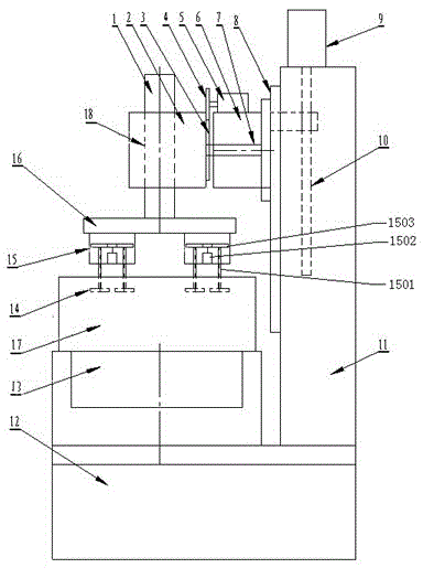
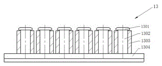
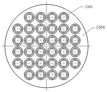
[0036] See figure 1 , the magnetorheological polishing device provided by the present invention comprises a base 12 and a frame 11 located on one side of the base 12, the base 12 is provided with a magnetic field generating device 13, and the magnetic field generating device 13 is provided with a magneto-rheological fluid. The polishing liquid tank 17 is provided with a lifting mechanism on the frame 11, and the lifting mechanism is provided with a workpiece drive mechanism that clamps the workpiece 14 above the polishing liquid tank 17 and makes the workpiece 14 move with multiple degrees of freedom; The lifting mechanism includes a servo motor 9 and a sliding seat 6 arranged on the frame 11, the servo motor 9 is connected with the sliding seat 6 through a ball screw 10, and the sliding seat 6 is installed on the guide rail 8 arranged vertically along the frame 11; The workpiece driving mechanism includes a swing mechanism arranged on the lifting mechanism, a revolution mecha...

Embodiment 2

[0045] See Figure 5 , the workpiece driving mechanism in this embodiment includes a lifting mechanism, a revolution mechanism arranged on the lifting mechanism, a rocking mechanism arranged on the revolution mechanism, and an autorotation mechanism arranged between the revolution mechanism and the rocking mechanism; The difference between example and embodiment 1 is that the swing servo motor 5, slide seat 6, swing main shaft 7, gears 3, 4 are canceled, and the head 2 is directly installed on the slide seat 6, and the structure of the workpiece moving frame 15 is different. Others are the same. Described revolution mechanism comprises the revolution servomotor 1 that is located on the machine head 2, revolution big disk 16 and workpiece motion frame 15, revolution servo motor 1 is connected with revolution large disk 16 by revolution main shaft 18, and workpiece motion frame 15 is a plurality of being located at revolution Below the large plate 16; the workpiece movement fra...

Embodiment 3

[0050] The workpiece driving mechanism in this embodiment includes a lifting mechanism, a revolution mechanism and a rotation mechanism arranged on the lifting mechanism; the difference from Embodiment 2 is that the revolution mechanism and the rotation mechanism in this embodiment are planetary motion mechanisms, such as Figure 9 As shown, it includes the workpiece moving frame 15 arranged under the machine head 2, the workpiece moving frame 15 includes a ring gear 1516, the upper and lower main shaft gears 1519, 1517 of the coaxial 1520 arranged in the ring gear 1516 and the upper and lower main shaft gears 1519, 1517 which are movable on the ring gear 1516 The workpiece shaft 1501, the revolving servo motor 1 provided on the machine head 2 meshes with the ring gear 1516 and the upper main shaft gear 1519 through the gear 1515 on the revolving main shaft 18, and the workpiece shaft 1501 meshes with the lower main shaft gear 1517 through the workpiece gear 1518, The workpiece...


PUM


Abstract

The invention discloses a magnetorheological polishing method and device. The method includes the steps that a workpiece is arranged in magnetorheological fluid with a magnetic field and does motion in at least two degrees of freedom, and therefore the surface of the workpiece is polished. The magnetorheological polishing method is characterized in that in the magnetorheological fluid with the magnetic field, the workpiece does motion in multiple degrees of freedom, under the effect of the gradient magnetic field, as the magnetorheological fluid in the fluid form will become the liquid solid state with the forced bonding elastic effect, a flux linkage formed in the direction of a magnetic line of force will clamp abrasive particles, and it amounts to a small soft magnetic grinding head; the workpiece and the magnetorheological fluid generates relative motion, the motion in multiple degrees of freedom of the workpiece is controlled, and therefore the outer surface/outer surfaces of one or more workpieces can be polished at the same time through one-time clamping; and the outer surfaces of the workpieces can be planes, arc faces or complex surfaces.

Description

technical field [0001] The invention belongs to magnetorheological polishing technology, in particular to a magnetorheological polishing method and device. Background technique [0002] With the continuous advancement of modern information electronics technology and optical technology, more and more ultra-smooth components are used in the IT and electronics industries, such as sapphire substrates, single crystal silicon surfaces, mobile phone back covers, etc. The processing batches of such components are large , its surface should meet the requirements of ultra-smooth, high gloss, uniform color and no scratches. At present, the grinding and polishing machines on the market all adopt the principle of plane mutual grinding. The workpiece is stuck in the center wheel and polished under the grinding action of the upper and lower polishing discs. The limitation of this polishing method is that it can only process flat surfaces, not curved surfaces such as curved surfaces. [0...

Claims


Application Information

Patent Timeline
IPC IPC(8): B24B1/00
CPCB24B1/005
Inventor 许亮陈永福杜群波许君
Owner YUHUAN CNC MACHINE TOOL
Why Eureka
Try Eureka