A magnetorheological polishing method and device
A magnetorheological polishing and magnetorheological fluid technology, applied in the field of magnetorheological polishing, can solve the problems of inability to process complex curved workpieces, complicated devices, etc., and achieve the effect of solving difficult polishing, reducing processes, and simplifying equipment structure.
- Summary
- Abstract
- Description
- Claims
- Application Information
AI Technical Summary
Problems solved by technology
Method used
Image
Examples
Embodiment 1
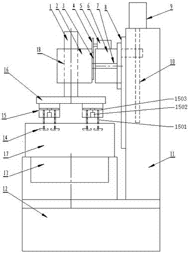
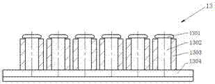
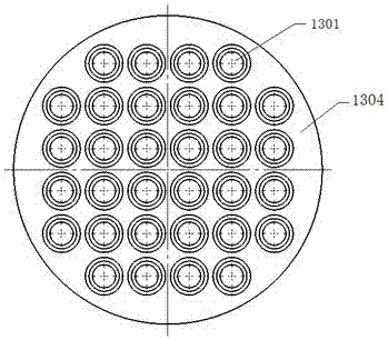
[0036] See figure 1 , the magnetorheological polishing device provided by the present invention comprises a base 12 and a frame 11 located on one side of the base 12, the base 12 is provided with a magnetic field generating device 13, and the magnetic field generating device 13 is provided with a magneto-rheological fluid. The polishing liquid tank 17 is provided with a lifting mechanism on the frame 11, and the lifting mechanism is provided with a workpiece drive mechanism that clamps the workpiece 14 above the polishing liquid tank 17 and makes the workpiece 14 move with multiple degrees of freedom; The lifting mechanism includes a servo motor 9 and a sliding seat 6 arranged on the frame 11, the servo motor 9 is connected with the sliding seat 6 through a ball screw 10, and the sliding seat 6 is installed on the guide rail 8 arranged vertically along the frame 11; The workpiece driving mechanism includes a swing mechanism arranged on the lifting mechanism, a revolution mecha...
Embodiment 2
[0045] See Figure 5 , the workpiece driving mechanism in this embodiment includes a lifting mechanism, a revolution mechanism arranged on the lifting mechanism, a rocking mechanism arranged on the revolution mechanism, and an autorotation mechanism arranged between the revolution mechanism and the rocking mechanism; The difference between example and embodiment 1 is that the swing servo motor 5, slide seat 6, swing main shaft 7, gears 3, 4 are canceled, and the head 2 is directly installed on the slide seat 6, and the structure of the workpiece moving frame 15 is different. Others are the same. Described revolution mechanism comprises the revolution servomotor 1 that is located on the machine head 2, revolution big disk 16 and workpiece motion frame 15, revolution servo motor 1 is connected with revolution large disk 16 by revolution main shaft 18, and workpiece motion frame 15 is a plurality of being located at revolution Below the large plate 16; the workpiece movement fra...
Embodiment 3
[0050] The workpiece driving mechanism in this embodiment includes a lifting mechanism, a revolution mechanism and a rotation mechanism arranged on the lifting mechanism; the difference from Embodiment 2 is that the revolution mechanism and the rotation mechanism in this embodiment are planetary motion mechanisms, such as Figure 9 As shown, it includes the workpiece moving frame 15 arranged under the machine head 2, the workpiece moving frame 15 includes a ring gear 1516, the upper and lower main shaft gears 1519, 1517 of the coaxial 1520 arranged in the ring gear 1516 and the upper and lower main shaft gears 1519, 1517 which are movable on the ring gear 1516 The workpiece shaft 1501, the revolving servo motor 1 provided on the machine head 2 meshes with the ring gear 1516 and the upper main shaft gear 1519 through the gear 1515 on the revolving main shaft 18, and the workpiece shaft 1501 meshes with the lower main shaft gear 1517 through the workpiece gear 1518, The workpiece...
PUM
 Abstract
Description
Claims
Application Information
 - R&D
- Intellectual Property
- Life Sciences
- Materials
- Tech Scout
- Unparalleled Data Quality
- Higher Quality Content
- 60% Fewer Hallucinations
Browse by: Latest US Patents, China's latest patents, Technical Efficacy Thesaurus, Application Domain, Technology Topic, Popular Technical Reports.
© 2025 PatSnap. All rights reserved.Legal|Privacy policy|Modern Slavery Act Transparency Statement|Sitemap|About US| Contact US: help@patsnap.com


