
A steel wire transmission joint with the function of compensating for the movement of the rope out

A technology of transmission joints and steel wires, applied in the field of transmission joints, can solve the problems of poor reliability of drive joints, low energy transmission efficiency, and small space for robots, and achieve the effects of small transmission errors, increased use range and space, and compact structure

Active Publication Date: 2017-06-13
HARBIN INST OF TECH
View PDF5 Cites 0 Cited by
  • Summary
  • Abstract
  • Description
  • Claims
  • Application Information

AI Technical Summary

Problems solved by technology

[0004] The present invention aims to solve the problems of poor reliability, low energy transmission efficiency and small use space of the robot in the existing drive joints, and further provides a steel wire drive joint with the function of compensating the movement of the rope outlet point

Method used


Image

  • A steel wire transmission joint with the function of compensating for the movement of the rope out
  • A steel wire transmission joint with the function of compensating for the movement of the rope out
  • A steel wire transmission joint with the function of compensating for the movement of the rope out

Examples


specific Embodiment approach 1

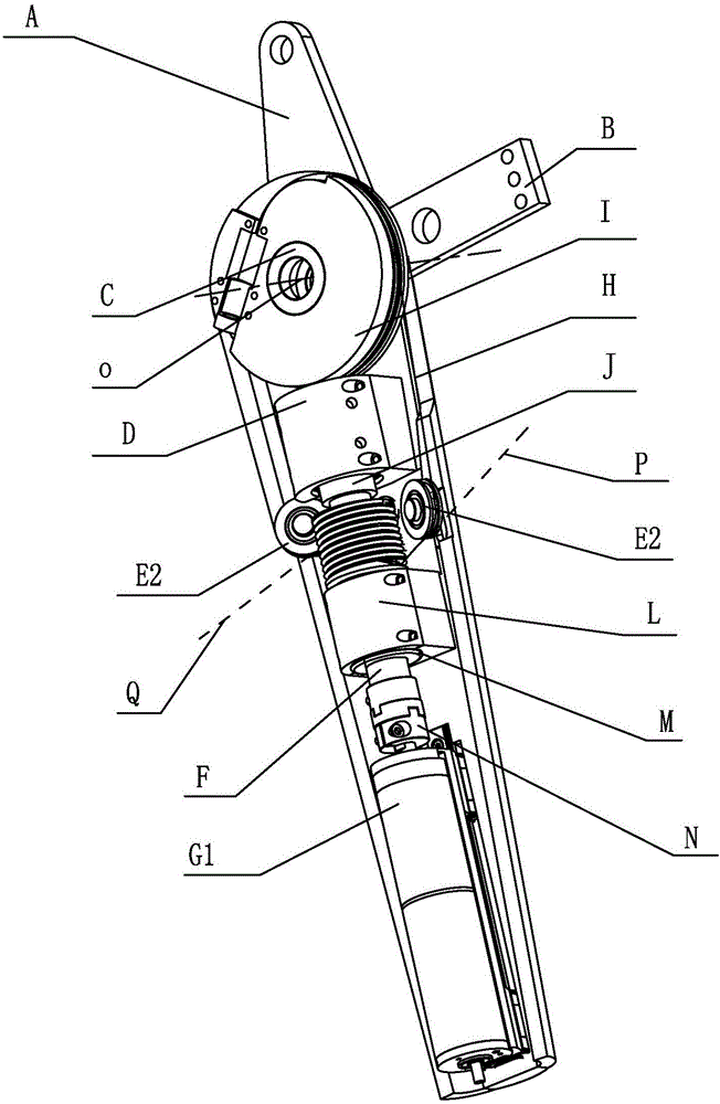
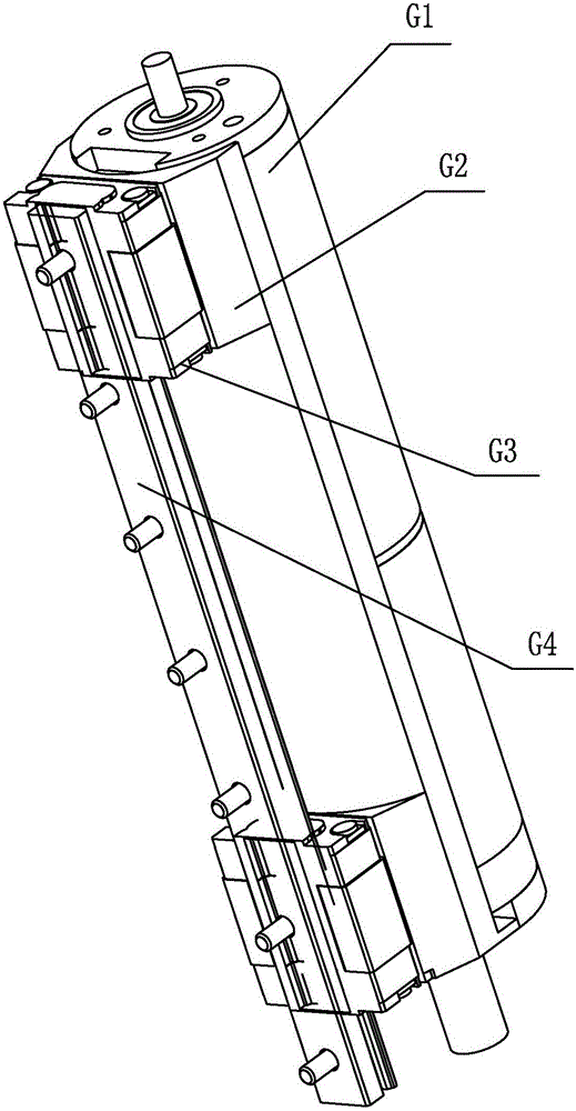
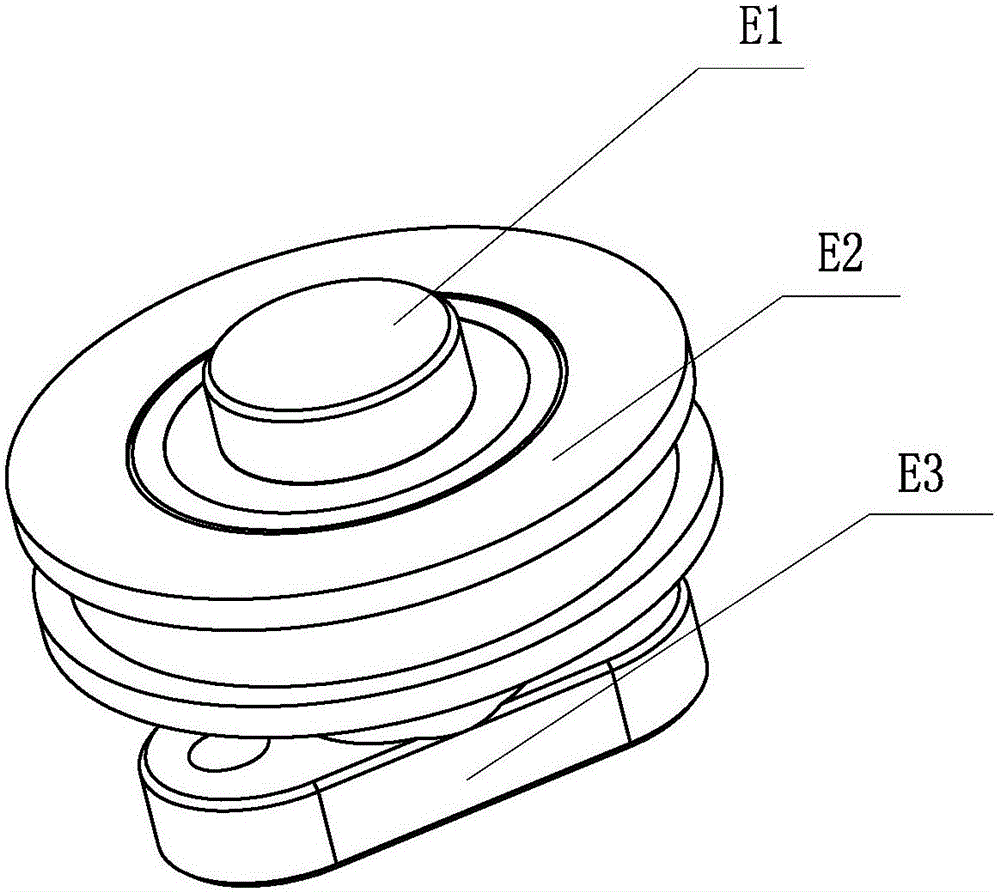
[0020] Specific implementation mode one: combine Figure 1-Figure 4 Illustrate, a kind of steel wire transmission joint with the movement compensation function of the rope outlet point of this embodiment, it comprises forearm and big arm; Screw pair, motor G1, linear bearing housing L, linear bearing M, wire rope H and two wire rope steering wheels E2; the boom includes bearing housing C and boom housing B;

[0021] The motor G1 is slidably installed on the forearm seat A, the motor G1 moves along the axial direction of the motor shaft, the output end of the motor G1 is connected with one end of the screw shaft F, the linear bearing seat L is installed on the forearm seat A, and the linear bearing M Installed on the linear bearing seat L, the screw shaft F is inserted on the linear bearing M, the other end of the screw shaft F is connected with the lead screw F2 of the screw pair, and the nut J of the screw pair is arranged on the forearm seat On the nut seat D on A, the scre...

specific Embodiment approach 2

[0023] Specific implementation mode two: combination figure 1 Note that the screw pair in this embodiment is a ball screw pair. With such setting, the transmission efficiency is high, and the operation is stable and reliable. Others are the same as in the first embodiment.

specific Embodiment approach 3

[0024] Specific implementation mode three: combination figure 1 It should be noted that the wire transmission joint with the function of compensating the movement of rope points in this embodiment further includes a coupling N through which the output end of the motor G1 is connected to the screw shaft F. With such setting, the dynamic performance of the shafting system is improved, and the operation is stable and reliable. Others are the same as in the first or second embodiment.


PUM


Abstract

The invention provides a steel wire transmission joint with the rope output point shifting compensation function and relates to a transmission joint suitable for robots in order to solve the problems that an existing drive joint is poor in reliability and low in energy transmission efficiency and accordingly the use space of a robot is small. The transmission joint comprises a small arm and a large arm. The small arm comprises a small arm base, a steel wire rope wheel, a nut base, a lead screw shaft, a lead screw pair, a motor, a linear bearing base, a linear bearing, a steel wire rope and two steel wire rope steering wheels. The large arm comprises a bearing base and a large arm base. The motor is installed on the small arm base in a sliding mode, a steel wire rope threaded wheel disc is fixedly installed on the lead screw shaft and distributed between the nut base and the linear bearing base, the two sides of the steel wire rope threaded wheel disc are each provided with one steel wire rope steering wheel, and the steel wire rope steering wheels are rotationally installed on the small arm base. The small arm base is rotationally connected with the large arm base through a bearing installed on the bearing base. The steel wire rope wheel is installed on the bearing base. The transmission joint is used for a robot.

Description

technical field [0001] The invention relates to a transmission joint suitable for a robot, in particular to a high-efficiency cross-axis steel wire transmission joint capable of automatically compensating the movement of the rope exit point of a sheave. Background technique [0002] A robot is a machine device that performs work automatically. It can accept human command, run pre-programmed programs, and act according to principles formulated with artificial intelligence technology. Its mission is to assist or replace human work in jobs such as manufacturing, construction, or hazardous jobs. Robots are mainly divided into industrial robots, stationary robots and mobile robots. The core of the robot structure is the robot's joints, and any movement of the robot is composed of rotating joints. Industrial robots are completely composed of rotating joints in series, and the linkage between each joint realizes various positions and postures of the robot to achieve different ef...

Claims


Application Information

Patent Timeline
Patent Type & Authority Patents(China)
IPC IPC(8): B25J17/00B25J9/10
CPCB25J9/104B25J17/00
Inventor 朱延河蔡雪风赵杰
Owner HARBIN INST OF TECH
Learn More