Multi-functional integral drier and implementation method thereof

A drying machine and multi-functional technology, which is applied in the direction of pretreatment equipment, pressure impregnation, wood processing equipment, etc., can solve the problems of poor use effect, low production efficiency, uneven heating, etc., and achieve convenient heat control and high production efficiency , good fuel injection effect

Active Publication Date: 2016-04-06
东阳市尚德电器机械有限公司
View PDF5 Cites 1 Cited by
  • Summary
  • Abstract
  • Description
  • Claims
  • Application Information

AI Technical Summary

Problems solved by technology

[0003] (1), low production efficiency;
[0004] (2) Uneven heating and poor drying effect;
[0005] (3) Refueling cannot be carried out;
[0006] (4) The use effect is poor and cannot meet the needs of customers;
[0007] (5), the wood is easy to deform and has poor stability

Method used


Image

  • Multi-functional integral drier and implementation method thereof
  • Multi-functional integral drier and implementation method thereof

Examples


Embodiment 1

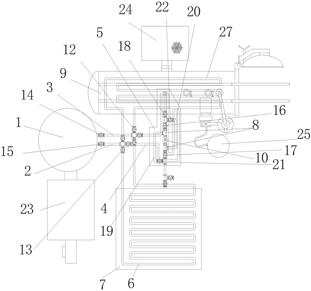
[0042] Such as figure 1 As shown, a multi-functional integrated dryer includes a heat transfer oil furnace. The heat transfer oil furnace is connected with a heat transfer oil circulation pipe outlet pipe and a heat transfer oil circulation pipe return pipe. The heat transfer oil circulation pipe outlet pipe is connected to one end of the first heating pipe. The other end of a heating pipe is connected to the return pipe of the heat transfer oil circulation pipe, and the first heating pipe enters the oil tank; the outlet pipe of the heat transfer oil circulation pipe is connected to one end of the second heating pipe, and the other end of the second heating pipe is connected to the return pipe of the heat transfer oil circulation pipe, The heating pipe enters into the oil storage tank; the oil storage tank is connected to the box body through the outlet pipe of the oil pipe, the oil pump is arranged on the outlet pipe of the oil pipe, and the outlet pipe of the oil pipe is arra...

Embodiment 2

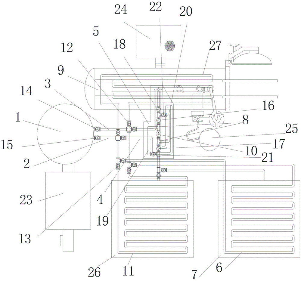
[0058] Such as figure 2 As shown, the difference between this embodiment and Embodiment 1 is that the inlet end of the sixth valve in this embodiment is connected to one end of the first "U"-shaped pipe, and the other end of the first "U"-shaped pipe is connected to the fifth valve and Between the oil pumps, one end of the second "U"-shaped pipe is connected between the sixth valve and the oil pump, and the other end of the second "U"-shaped pipe is connected between the fifth valve and the oil outlet valve; the first "U"-shaped pipe There is a seventh valve on the top, and an eighth valve on the second "U"-shaped pipe; it also includes a third heating pipe, which leads into the box, and one end of the third heating pipe is connected to the outlet pipe of the heat transfer oil circulation pipe , the other end of the third heating pipe is connected to the return pipe of the heat transfer oil circulation pipe.

[0059] This embodiment also includes a wax tank, the fourth heati...


PUM


Abstract

The invention discloses a multi-functional integral drier. The multi-functional integral drier comprises a heat conducting oil furnace, wherein a heat conduction oil circulating exhaust pipe and a heat conducting oil circulating return pipe are connected to the heat conducting oil furnace, the heat conducting oil circulating exhaust pipe is connected with one end of a first heating pipe, the other end of the first heating pipe is connected with the heat conducting oil circulating return pipe, and the first heating pipe enters an oil groove; the heat conducting oil circulating exhaust pipe is connected with one end of a second heating pipe, the other end of the second heating pipe is connected with the heat conducting oil circulating return pipe, and the second heating pipe enters an oil storage tank; the oil storage tank is connected to a tank body through oil exhaust pipes, and an oil pump is arranged on the oil exhaust pipes which are arranged in the oil groove; the tank body is connected with a high frequency generator. The invention further discloses an implementation method of the multi-functional integral drier. The multi-functional integral drier disclosed by the invention has the characteristics of being simple in structure, low in building cost, high in production efficiency, broad in application scope, good in timber stability, good in use effects and the like.

Description

technical field [0001] The invention relates to wood drying technology, in particular to a multifunctional integrated dryer and its realization method. Background technique [0002] Existing dryers use stainless steel condensing sheets on the side, and the water will drip after condensation, so awnings and welding parts are required. Such as Chinese patent, patent number: 201120281493.2, a rectangular high-frequency vacuum combined dryer, including a high-frequency heating device, a vacuum box, a water storage tank, a vacuum pump system, a timber car and a track, the shape of the vacuum box and each front section are Rectangular, the vacuum box is equipped with a built-in condenser, and the outside of the vacuum box is provided with an insulation layer; however, the following technical problems still exist: [0003] (1) Low production efficiency; [0004] (2) Uneven heating and poor drying effect; [0005] (3) Refueling cannot be carried out; [0006] (4) The use effect ...

Claims


Application Information

Patent Timeline
Patent Type & Authority Applications(China)
IPC IPC(8): B27K3/10B27K3/02
CPCB27K3/0214B27K3/10
Inventor 包淳德
Owner 东阳市尚德电器机械有限公司
Why Eureka
Try Eureka